
LED lamp

A technology for LED lamps and LED wicks, which can be applied to cooling/heating devices of lighting devices, lighting and heating equipment, semiconductor devices of light-emitting elements, etc., can solve the problems of complex process and high cost

Inactive Publication Date: 2015-06-24
苏睿
View PDF3 Cites 0 Cited by
  • Summary
  • Abstract
  • Description
  • Claims
  • Application Information

AI Technical Summary

Problems solved by technology

[0003] In the existing LED lamps, when the bulb of the LED lamp is damaged or does not meet the requirements for use, the entire lamp needs to be replaced. It is convenient and low-cost to change the needs of lighting environment changes, so it is necessary to carry out technical transformation to upgrade products to meet customer needs

Method used


Image

  • LED lamp

Examples


Embodiment Construction

[0015] The principles and features of the present invention are described below in conjunction with the accompanying drawings, and the examples given are only used to explain the present invention, and are not intended to limit the scope of the present invention.

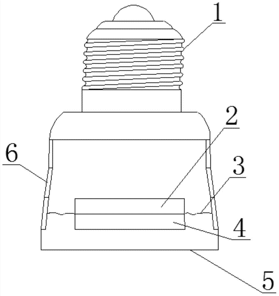
[0016] Such as figure 1 As shown, an LED lamp includes a joint 1, a heat dissipation ring 6, a substrate 3, an LED driver 2, an LED wick 4 and a bulb 5, the heat dissipation ring 6 is placed at the lower end of the joint 1, and the substrate 3 is placed at the heat dissipation ring 6 Inside the lower end of the base plate 3, the LED driver 2 is placed on the upper end surface of the substrate 3, the bulb 5 is placed on the lower end of the heat dissipation ring 6, and the bottom surface of the base plate 3 is provided with a reflective layer, and the reflective layer can make the light diffusely reflect. It can effectively reflect the light, and the diffuse reflection can make the light reflect not too dazzling.

...


PUM


Abstract

The invention relates to an LED lamp which comprises a connector, a radiating ring, a substrate, an LED driver, an LED lamp core and a bulb. The radiating ring is disposed at the lower end of the connector. The substrate is disposed inside the lower end of the radiating ring. The LED driver is disposed on the upper end face of the substrate. The bulb is disposed at the lower end of the radiating ring. A reflecting layer is disposed at the bottom of the substrate. The reflecting layer can allow light rays to generate diffuse reflection. Compared with the prior art, the LED lamp can change LED lighting directions and change light environments and is low in cost.

Description

technical field [0001] The invention relates to the field of lighting, in particular to an LED lamp. Background technique [0002] Recently, instead of incandescent lamps with high power consumption, there is an increasing demand for LED lamps that consume less power and use LEDs as light sources. [0003] In the existing LED lamps, when the bulb of the LED lamp is damaged or does not meet the requirements for use, the entire lamp needs to be replaced. It is necessary to change the changing lighting environment conveniently and at low cost, so it is necessary to carry out technical transformation to upgrade the product to meet customer needs. Contents of the invention [0004] The technical problem to be solved by the present invention is to provide a low-cost LED lamp that can change the direction of LED illumination and change the lighting environment. [0005] The technical solution of the present invention to solve the above-mentioned technical problems is as follows...

Claims


Application Information

Patent Timeline
IPC IPC(8): F21S2/00F21V29/89F21V19/02F21V7/00F21Y101/02F21K9/232F21K9/60F21Y115/10
CPCF21S2/00F21V7/00F21V19/02F21Y2101/00
Inventor 苏睿
Owner 苏睿
Learn More