Oval vibration auxiliary cutting micro-groove feature modeling method

A technology of elliptical vibration and modeling method, which is applied in the direction of instruments, digital control, control/regulation systems, etc.

Inactive Publication Date: 2015-06-24
NANJING UNIV OF AERONAUTICS & ASTRONAUTICS
View PDF2 Cites 20 Cited by
  • Summary
  • Abstract
  • Description
  • Claims
  • Application Information

AI Technical Summary

Problems solved by technology

At present, the research of scholars rarely involves the mathematical modeling and analysis of the surface of the workpiece, and the modeling and simulation before the actual vibration cutting experiment has an important reference and guiding significance for the whole experiment.

Method used


Image

  • Oval vibration auxiliary cutting micro-groove feature modeling method
  • Oval vibration auxiliary cutting micro-groove feature modeling method
  • Oval vibration auxiliary cutting micro-groove feature modeling method

Examples


Embodiment Construction

[0074] The technical solution of the present invention will be described in detail below in conjunction with the accompanying drawings.

[0075] 1. a method for modeling the shape of elliptical vibration-assisted cutting micro-grooves, is characterized in that comprising the steps:

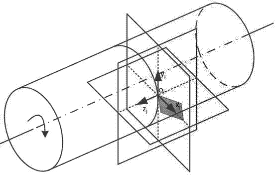
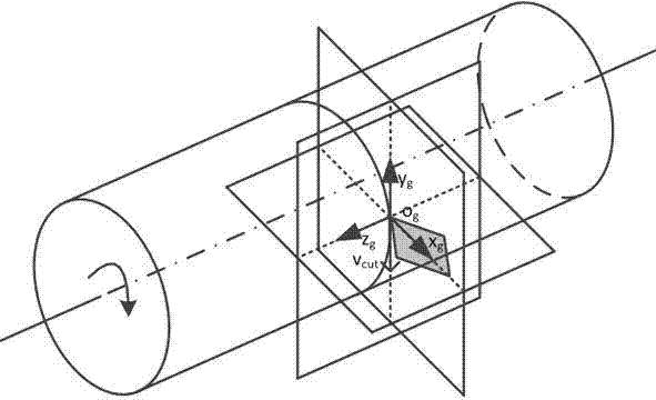
[0076] (1) Establish machine tool processing coordinate system o j -x j the y j z j , workpiece coordinate system o g -x g the y g z g , tool coordinate system o d -x d the y d z d and elliptical vibration assisted cutting local coordinate system o z -x z the y z z z , the above coordinate systems are all right-handed Cartesian standard Cartesian coordinate systems.

[0077] Establish the machining coordinate system of the machine tool: take the initial contact point of the turning tool nose arc curve and the workpiece as the coordinate origin o j point o j The plane where the point and workpiece axis are located is x j o j z j plane, where o j z j The axis is parallel to the...


PUM


Abstract

The invention discloses an ultrasound oval vibration auxiliary turning micro-groove feature modeling method and belongs to the field of numerical control machining. The method comprises the steps that a machine tool machining coordinate system, a workpiece coordinate system, a tool coordinate system and a local coordinate system for oval vibration auxiliary cutting are established; a turning tool point circular curve equation and a tool ultrasound oval vibration cutting track equation are established with the surface of a machined workpiece as a criterion according to machining parameters and oval vibration parameters in the direction perpendicular to the cutting direction; the turning tool point circular curve equation and the tool ultrasound oval vibration cutting track equation are converted into the workpiece coordinate system; in the workpiece coordinate system, a turning tool point circular curve sweeps along the converted ultrasound oval vibration cutting tracks to form a spatial tool point vibration curved face; the tool point vibration curved face between adjacent oval vibration track intersecting lines is reserved by calculating intersecting lines between the adjacent oval vibration tracks so that micro-groove surface feature of the surface of a workpiece can be formed. The ultrasound oval vibration auxiliary turning micro-groove feature modeling method can solve the problem of oval vibration auxiliary cutting micro-groove surface feature generation.

Description

technical field [0001] The invention belongs to the field of numerical control machining, in particular to the field of micro-groove surface modeling caused by high-frequency vibration of a tool in ultrasonic elliptical vibration turning. Background technique [0002] With the rapid development of precision and ultra-precision machining technology, elliptical vibration cutting has been widely concerned because of its advantages of reducing cutting force, improving machining quality, suppressing workpiece burrs, and increasing tool life. In view of the higher and higher requirements for the processing quality of high-precision parts, scholars have designed a variety of elliptical vibration cutting methods and supporting vibration cutting devices to further improve the surface quality of elliptical vibration cutting. During the elliptical vibration cutting process, the vibratory cutting vibration of the tool produces a continuous overlapping elliptical trajectory relative to t...

Claims


Application Information

Patent Timeline
Patent Type & Authority Applications(China)
IPC IPC(8): G05B19/19
CPCG05B19/19G05B2219/33003G05B2219/45136
Inventor 张臣史桂林李迎光周来水
Owner NANJING UNIV OF AERONAUTICS & ASTRONAUTICS
Why Eureka
Try Eureka