Charge pump

A charge pump and charge control technology, which is applied in the field of charge pumps, can solve the problems of large influence of charge and discharge current mismatch, smaller voltage output range, charge and discharge current mismatch, etc., to achieve the effect of widening the effective working range

Active Publication Date: 2015-06-24
INST OF ELECTRONICS CHINESE ACAD OF SCI
View PDF6 Cites 3 Cited by
  • Summary
  • Abstract
  • Description
  • Claims
  • Application Information

AI Technical Summary

Problems solved by technology

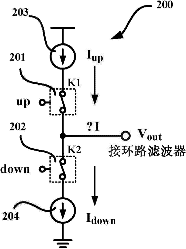
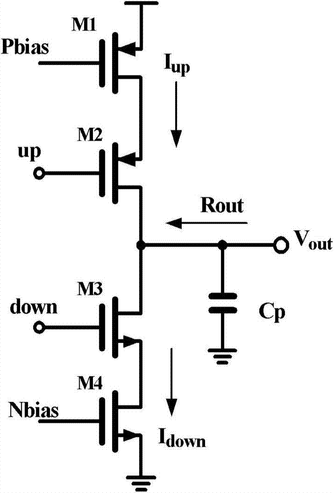
The source and drain voltages of MOS transistors M1 and M2 are affected by V out changes with changes, so the charging current I up and discharge current I down are subject to V out The influence of the channel modulation effect caused by the charge and discharge current mismatch
image 3 Shown is the charge pump charging current I up and discharge current I down With the output voltage V out Variation curve, the charge and discharge current mismatch degree is greatly affected by the output voltage change, resulting in a smaller voltage output range

Method used


Image

  • Charge pump
  • Charge pump
  • Charge pump

Examples


Embodiment Construction

[0029] In order to make the object, technical solution and advantages of the present invention clearer, the present invention will be described in further detail below in conjunction with specific embodiments and with reference to the accompanying drawings. It should be noted that, in the drawings or descriptions of the specification, similar or identical parts all use the same figure numbers. Implementations not shown or described in the accompanying drawings are forms known to those of ordinary skill in the art. Additionally, while illustrations of parameters including particular values ​​may be provided herein, it should be understood that the parameters need not be exactly equal to the corresponding values, but rather may approximate the corresponding values ​​within acceptable error margins or design constraints.

[0030] The invention proposes a charge pump with a novel feedback circuit structure to reduce the charge-discharge current mismatch of the charge pump and expa...


PUM


Abstract

The invention provides a charge pump. The charge pump is detected by a feedback module to output the voltage, and power source current values mirrored by charging and discharging power sources of the charge pump are adjusted according to the value of the output voltage of the charge pump, so that charging and discharging current mismatching caused by changes of the output voltage is compensated.

Description

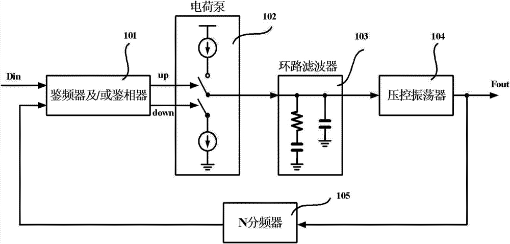
technical field [0001] The invention relates to the field of electronic components, in particular to a charge pump. Background technique [0002] In recent years, the phase-locked loop (PLL) of the charge pump has been widely used in various electronic devices because of its ability to provide accurate and low-jitter clock signals. figure 1 It is a structural schematic diagram of an integer frequency division charge pump phase-locked loop in the prior art, which includes a frequency detector and / or a phase detector (Frequency Detector / Phase Detector) 101, a charge pump (Charge Pump, CP) 102, a loop filter A Low Pass Filter (LPF) 103 , a Voltage Control Oscillator (Voltage Control Oscillator, VCO) 104 , and a divider by N frequency divider (Divider) 105 . The schematic diagram of the circuit structure is also applicable to a phase-locked loop in a clock and data recovery circuit (Clock and Data Recovery, CDR). Wherein the charge pump 102 is an important module in the phase-...

Claims


Application Information

Patent Timeline
Patent Type & Authority Applications(China)
IPC IPC(8): H02M3/07
CPCH02M3/07
Inventor 杨海钢何辉刘飞韦援丰陈柱佳屈小钢张春红杨雅娟
Owner INST OF ELECTRONICS CHINESE ACAD OF SCI
Why Eureka
Try Eureka