
Trapezoid color steel tile roof photovoltaic assembly installing structure

A photovoltaic module and installation structure technology, applied in the support structure of photovoltaic modules, photovoltaic modules, photovoltaic power generation, etc., can solve the problems of fast aging of waterproof rubber pads, difficulty in securing and fixing solar photovoltaic modules, etc., and improve waterproof efficiency , improve the service life and reduce the hidden danger of roof leakage

Inactive Publication Date: 2015-06-24
尹立胜
View PDF6 Cites 4 Cited by
  • Summary
  • Abstract
  • Description
  • Claims
  • Application Information

AI Technical Summary

Problems solved by technology

[0002] With the rise of distributed solar power plants in China, it is necessary to solve the problem of combining different roofs and solar modules; the trapezoidal color steel tile roof is characterized by a small upper end and a larger lower end of the wave crest, and it is impossible to fix solar photovoltaic modules with conventional clamping devices. It can only be connected by piercing the roof for fixing. If the roof is pierced through, the waterproof problem of the pierced position must be considered. The mode of pressing and fixing with ordinary drilling screws and rubber pads, the sun and ultraviolet rays on the roof, high temperature Under the influence of low temperature, low temperature, etc., the aging speed of the waterproof rubber mat is relatively fast, and it is difficult to ensure that there will be no water leakage at the roof penetration position within the 25-year service life of the photovoltaic power station
[0003] Therefore, in order to overcome the deficiencies of the above-mentioned technologies and design a trapezoidal color steel tile roof photovoltaic module installation structure that can avoid the roof water leakage caused by the aging of the rubber mat in a short period of time, it is the problem that the inventor wants to solve

Method used


Image

  • Trapezoid color steel tile roof photovoltaic assembly installing structure
  • Trapezoid color steel tile roof photovoltaic assembly installing structure
  • Trapezoid color steel tile roof photovoltaic assembly installing structure

Examples


Embodiment Construction

[0022] The present invention will be further described below in conjunction with specific examples. It should be understood that these examples are only used to illustrate the present invention and are not intended to limit the scope of the present invention. In addition, it should be understood that after reading the teachings of the present invention, those skilled in the art can make various changes or modifications to the present invention, and these equivalent forms also fall within the scope defined by the appended claims of the application.

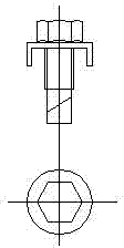
[0023] image 3 It is a schematic diagram of the structure of the buckle type drill end screw in the present invention.

[0024] Figure 4 It is a top view structural diagram of the trapezoidal mounting seat of the present invention.

[0025] Figure 5 It is a schematic diagram of the front view structure of the trapezoidal mounting seat of the present invention.

[0026] Figure 6 It is a schematic diagram of the side vie...


PUM


Abstract

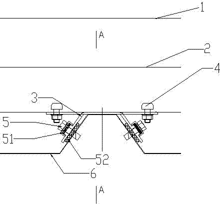
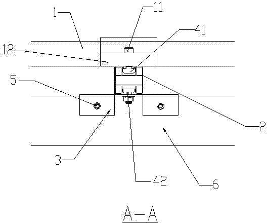
The invention discloses a trapezoid color steel tile roof photovoltaic assembly installing structure. A trapezoid installing base is fixed to a peak of a trapezoid color steel tile roof through plate buckle type self-drilling screws, an aluminum guide rail is connected with the trapezoid installing base through fastener bolts, and a solar photovoltaic assembly is laid and fixed on the aluminum guide rail. Foam adhesive tape is arranged on the contact face of the trapezoid installing base and the trapezoid color steel tile roof, so that loosening, caused by thermal expansion and cold contraction of materials, of the plate buckle type self-drilling screws is prevented. Waterproof rubber pads are installed at the plate-shaped positions of the plate buckle type self-drilling screws, adverse influences of solar ultraviolet and environments on the waterproof rubber pads are reduced, and the service life of the rubber pad is greatly prolonged. By means of the maze type sealing design, even if the waterproof rubber pads age to a certain degree, a boss of the trapezoid installing base can effectively prevent water flow from directly entering from prefabricated holes, waterproof efficiency is improved, and the hidden hazard that the roof leaks water is reduced.

Description

technical field [0001] The invention relates to the technical field of a trapezoidal color steel tile roof photovoltaic module installation structure, in particular to a trapezoid color steel tile roof photovoltaic module installation structure. Background technique [0002] With the rise of distributed solar power plants in China, it is necessary to solve the problem of combining different roofs and solar modules; the trapezoidal color steel tile roof is characterized by a small upper end and a larger lower end of the wave crest, and it is impossible to fix solar photovoltaic modules with conventional clamping devices. It can only be connected by piercing the roof for fixing. If the roof is pierced through, the waterproof problem of the pierced position must be considered. The mode of pressing and fixing with ordinary drilling screws and rubber pads, the sun and ultraviolet rays on the roof, high temperature Under the influence of low temperature, low temperature, etc., the...

Claims


Application Information

Patent Timeline
IPC IPC(8): H02S20/25
CPCH02S20/00F24S25/615Y02B10/10Y02B10/20Y02E10/47Y02E10/50
Inventor 尹立胜信丽娜
Owner 尹立胜
Learn More