Controllable oscillator and method thereof

A controllable oscillator technology, applied in power oscillators, electrical components, etc., can solve problems such as phase noise and performance degradation, and achieve the effect of suppressing noise

Inactive Publication Date: 2015-06-24
REALTEK SEMICON CORP
View PDF3 Cites 6 Cited by
  • Summary
  • Abstract
  • Description
  • Claims
  • Application Information

AI Technical Summary

Problems solved by technology

However, typical controllable oscillators suffer from performance degradation due to flicker noise caused by MOS transistors (i.e., 111, 112, 131, 132)
Here, the multiple MOS transistors modulate the oscillation and cause phase noise

Method used


Image

  • Controllable oscillator and method thereof
  • Controllable oscillator and method thereof
  • Controllable oscillator and method thereof

Examples


Embodiment Construction

[0016] The following detailed description refers to the accompanying drawings, which illustrate various practical embodiments of the present invention. The described embodiments are clear and fully disclosed, so that those skilled in the art can implement them accordingly. The different embodiments are not mutually exclusive, and some embodiments can be combined with one or more embodiments to form a new embodiment. Therefore, the following detailed description is not intended to limit the present invention.

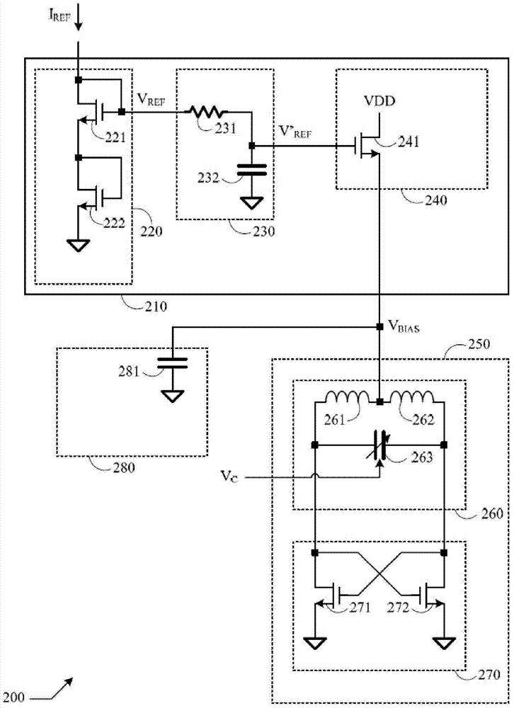
[0017] figure 2 It is a schematic diagram of a controllable oscillator according to an embodiment of the invention. Reference figure 2 The controllable oscillator 200 includes a voltage-mode biasing network 210 and an oscillation core circuit 250. The voltage bias circuit 210 is coupled to the oscillation core circuit 250. The voltage bias circuit 210 receives a reference current I REF , And output a bias voltage V BIAS . Oscillation core circuit 250 receives bias v...


PUM


Abstract

An apparatus and related method include a voltage-mode biasing network for receiving a reference current and outputting a biasing voltage, and an oscillator core for receiving the biasing voltage and sustaining an oscillation, wherein the voltage-mode biasing network comprises a current-to-voltage converter for converting the reference current into a reference voltage, a low-pass filter for filtering the reference voltage into a filtered reference voltage, and a source follower for receiving the filtered reference voltage and outputting a biasing voltage. The oscillator core comprises a resonator coupled to a regenerative network. In an embodiment, the current-to-voltage converter comprises at least a diode-connected transistor.

Description

Technical field [0001] The invention relates to a controllable oscillator, especially to a low-noise controllable oscillator. Background technique [0002] figure 1 It is a schematic diagram of a known controllable oscillator. Reference figure 1 , The controllable oscillator 100 includes a current mirror 110. The current mirror 110 includes a plurality of P-channel metal oxide semiconductor (PMOS) transistors 111 and 112. Current mirror 110 receives reference current I REF , And output bias current I BIAS . The controllable oscillator 100 also includes an oscillation core circuit 140. The oscillating core circuit 140 includes a resonator 120, and the resonator 120 includes two inductors 121, 122 and controlled by a control voltage V C The variable capacitor 123. The resonator 120 receives the bias current I BIAS , And determine the oscillation frequency. The oscillator core circuit 140 also includes a regeneration circuit 130, and the regeneration circuit 130 includes two...

Claims


Application Information

Patent Timeline
Patent Type & Authority Applications(China)
IPC IPC(8): H03B5/04
CPCH03B5/1212H03B5/1228H03B5/1243H03B2200/0062
Inventor 林嘉亮
Owner REALTEK SEMICON CORP
Why Eureka
Try Eureka