Cooling system of cabinet

A heat dissipation system and cabinet technology, which is applied in the field of server cabinet heat dissipation systems, can solve the problems of temperature rise in the cabinet and device temperature, low efficiency, loss, etc.

Active Publication Date: 2015-06-24
SHENZHEN ENVICOOL TECH
View PDF8 Cites 25 Cited by
  • Summary
  • Abstract
  • Description
  • Claims
  • Application Information

AI Technical Summary

Problems solved by technology

[0007] The aforementioned cooling systems are roughly divided into two types: air-cooled cooling and liquid-cooled cooling. When the pipeline outside the cabinet fails or is abnormal, all the cold plates in the cabinet will stop working, which will easily cause the temperature in the cabinet and the device temperature to rise rapidly, causing losses, and the flow of the pipeline inside the cabinet cannot be adjusted
Moreover, in actual use, there are not only devices with low heat generation density that can be solved by air cooling in the cabinet, but also devices with high heat generation density that need to be cooled by water cooling. The heat dissipation scheme needs to independently set up water-cooled or air-cooled external heat dissipation methods to ensure the normal operation of the entire cabinet
Most of the air-cooled side adopts multi-unit backup to provide emergency heat dissipation in case of failure, while in the liquid-cooled mode, the failure of the main cooling pipe will often cause a large area of ​​thermal protection shutdown of the cabinet, resulting in huge losses

Method used


Image

  • Cooling system of cabinet
  • Cooling system of cabinet
  • Cooling system of cabinet

Examples


Embodiment 1

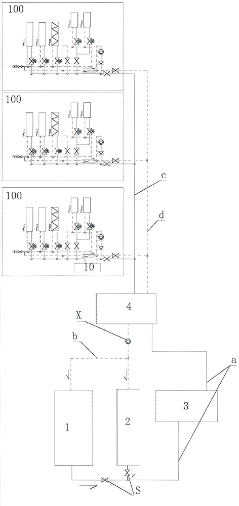
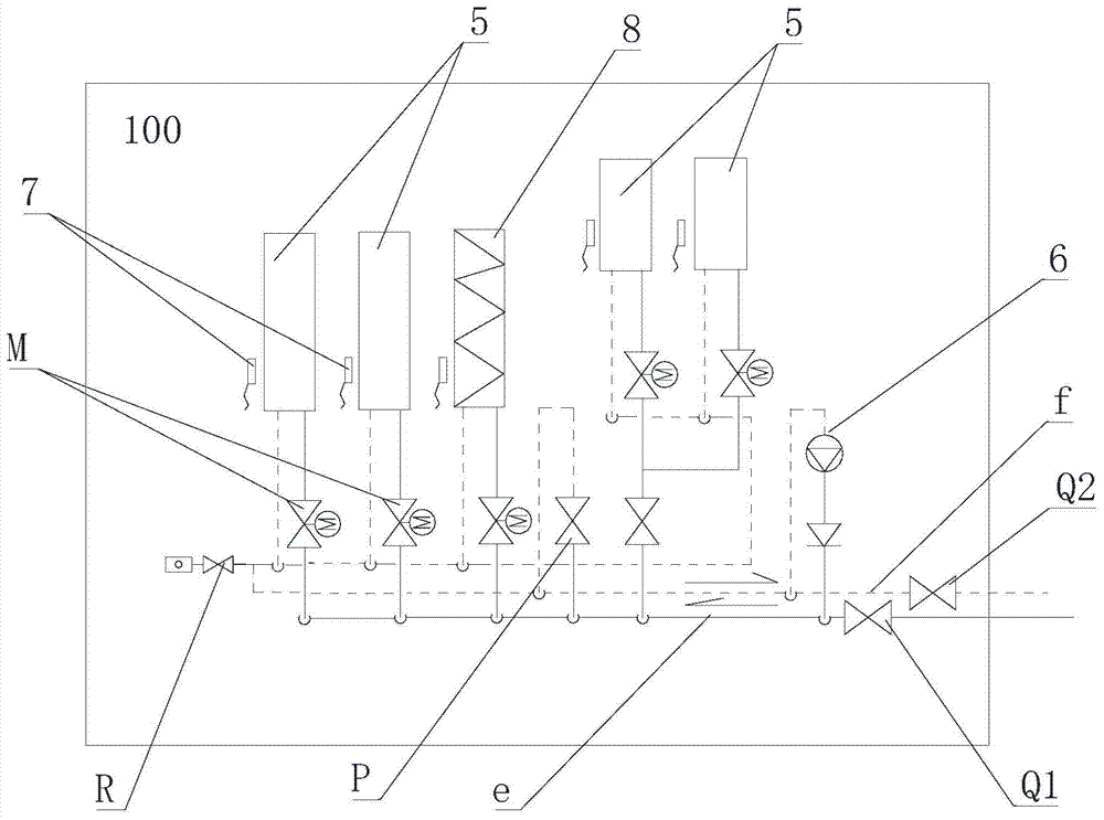
[0031] like figure 1 and figure 2 as shown,figure 1 , figure 2 The pipeline shown by the solid line in the middle is the working fluid inlet pipe, and the pipeline shown by the dotted line is the working fluid return pipe. The refrigerant flows through the pipeline, including phase change or non-phase change fluid. The heat dissipation system includes the external circulation system and the internal circulation system. Circulation system, the outer circulation system includes a cold source composed of a main cooling unit 1 and a secondary cooling unit 2, and a cold storage tank 3 connected to the cold source, and the outer circulation system and the inner circulation system are connected through an intermediate heat exchanger 4. The working medium inlet pipe a of the external circulation system passes through the cold storage tank 3 and is connected to the intermediate heat exchanger 4, and the working medium return pipe b of the external circulation system is connected to ...

Embodiment 2

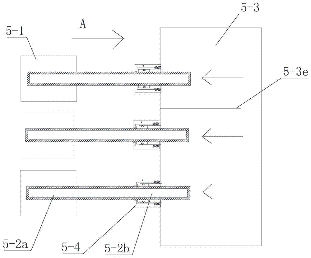
[0037] like image 3 and Figure 4 As shown, the liquid cooling radiator 5 of this embodiment includes a heat dissipation substrate 5-1, a heat pipe 5-2 and a centralized cooling pipe 5-3. The heat dissipation substrate 5-1 is in contact with the surface of the electronic device to be dissipated. The heat pipe 5-2 is connected to the heat dissipation substrate 5-1. Same as the prior art, the heat pipe 5-2 includes a heat pipe evaporation section 5-2a and a heat pipe condensation section 5-2b. The inner wall of the heat pipe is provided with a capillary structure. The heat pipe evaporation section 5-2a is connected to the heat dissipation substrate 1, and the heat dissipation substrate 5-1 conducts the heat on the surface of the electronic device to the heat pipe evaporation section 5-2a for heat dissipation. The condensing section 5-2b of the heat pipe extends into the concentrated cooling pipe 5-3, and is sealed and connected with the concentrated cooling pipe 5-3. In this...

Embodiment 3

[0040] refer to Figure 4 and Figure 5 , the difference between this embodiment and Embodiment 2 is that no intermediate partition is provided in the centralized cooling pipe, the centralized cooling pipe 5-3 is connected to a plurality of heat pipes 5-2, and the heat pipes 5-2 are arranged in a misplaced interval. 3d The cooling liquid entering the centralized cooling pipe 5-3 flows to the cooling liquid outlet pipe 5-3c through the heat pipe radiator 2 arranged in a staggered manner, so that the condensation end of each heat pipe can be cooled by the same temperature of the incoming liquid as much as possible, Guaranteed cooling effect.

[0041] Centralized cooling pipes are used to centrally dissipate heat from multiple heat pipes at the same time, and the coolant circulates in the centralized cooling pipes, which can dissipate heat for multiple electronic devices at one time, reduce the volume of the liquid cooling radiator, and improve the heat exchange efficiency. The...


PUM


Abstract

A cooling system of a cabinet comprises an outer circulating system and an inner circulating system. The outer circulating system comprises a cold source, a liquid storage tank and an outer circulating pump, and a working medium inlet pipe and a working medium outlet pipe of the outer circulating system are connected with a middle heat exchanger. The inner circulating system comprises a cabinet inner circulating sub-system, a working medium inlet pipe of the inner circulating system and a working medium outlet pipe of the inner circulating system. The cabinet inner circulating sub-system comprises liquid-cooling radiators, a cabinet inner work medium inlet connected with the working medium inlet pipe of the inner circulating system through an inlet check valve, a cabinet inner working medium return pipe connected with a working medium return pipe of the inner circulating system through an outlet check valve, and an air-cooling radiator. The air-cooling radiator is connected with the cabinet inner working medium inlet pipe and the cabinet inner working medium return pipe, a flow proportion adjusting valve is arranged between the air-cooling radiator and the cabinet inner working medium inlet pipe, the liquid-cooling radiators are connected with the cabinet inner working medium inlet pipe and the cabinet inner working medium return pipe, and a flow proportion adjusting valve is arranged between each liquid-cooling radiator and the cabinet inner working medium inlet pipe. The cooling system has the advantages of being high in cooling efficiency and capable of saving energy.

Description

technical field [0001] The invention relates to the technical field of heat dissipation and cooling, and more specifically, to a heat dissipation system for a server cabinet. Background technique [0002] In the communication and IT industry, a large number of standard cabinets are used to provide a physical installation environment for internal servers, switches, storage devices and other electronic devices. In order to provide heat dissipation for the equipment inside the cabinet, a large number of fans are used to take the heat inside the cabinet out of the cabinet, and then transfer the heat to the external environment through equipment such as air conditioners or fans in the room. As the heat consumption of electronic chips and power devices increases, the heat generated inside the cabinet continues to increase, and the air-cooled heat dissipation method can no longer meet the heat dissipation requirements of the internal equipment. [0003] In order to enhance the hea...

Claims


Application Information

Patent Timeline
Patent Type & Authority Applications(China)
IPC IPC(8): H05K7/20
Inventor 韦立川陈川吴刚王铁旺
Owner SHENZHEN ENVICOOL TECH
Why Eureka
Try Eureka