
Spray head for a fluid product and dispenser comprising such a spray head

A technology of fluid products and spray heads, which is applied in the field of spray heads of fluid products and distributors including such spray heads, which can solve the problems of uncontrolled, detrimental spray quality, pressure head loss, etc., and achieve pressure reduction Effect of head loss, minimization of laminar flow phenomenon, minimization of pressure head loss

Active Publication Date: 2015-06-24
APTAR FRANCE SAS
View PDF8 Cites 2 Cited by
  • Summary
  • Abstract
  • Description
  • Claims
  • Application Information

AI Technical Summary

Problems solved by technology

Moreover, the fact that the vortex follows the frusto-conical inner wall of the vortex chamber produces significant head losses and unwanted uncontrolled flow phenomena
[0004] In both embodiments of patent document FR-2 399 282, the atomization chamber becomes the cause of a large head loss and a jet phenomenon which impairs the flow through the spray hole. good quality of spray

Method used


Image

  • Spray head for a fluid product and dispenser comprising such a spray head
  • Spray head for a fluid product and dispenser comprising such a spray head
  • Spray head for a fluid product and dispenser comprising such a spray head

Examples


Embodiment Construction

[0023] The spray head of the present invention may be used at the outlet of any fluid dispensing device such as a pump, valve, squeezable reservoir, etc. The spray head according to the invention has a preferred application as a button which can be manually actuated by means of one or more fingers. The button can be integrated on a pump or a valve, or preferably attached to the free end of the actuating rod forming the internal output conduit. In the case of a pump, the actuating rod is provided with a piston which slides sealingly inside a cylinder formed in a pump body fixedly mounted on the opening of the reservoir. Pumps commonly comprise a pump chamber equipped with an inlet valve and an outlet valve which can be carried by an actuating rod. Thus, by inserting the actuating rod inside the pump body against the spring, the volume of the pump chamber is reduced thereby pressurizing the fluid it contains. From the moment the pressure reaches a predetermined value, the outl...


PUM


Abstract

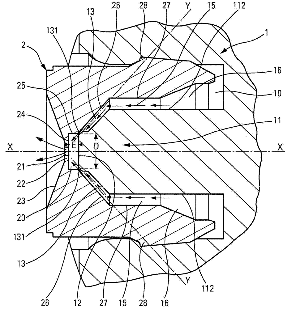
A spray head for a fluid product comprising: . a spray orifice (21), . a swirl chamber (20) comprising a bottom wall (12) and a side wall (25), and . swirl channels (13) respectively defining channel outlets (131) that open transversely to dispensing axis X in the swirl chamber (20), each channel (13) defining a spray axis Y that extends into the swirl chamber (20) from the channel outlet (131), the spray axes Y of the swirl channels (13) extending away from both the bottom wall (12) and the peripheral side wall (25) which are both adjacent to the channel outlets (131) in such a way as to pass through the swirl chamber (20) without passing along either the bottom wall (12) or the peripheral side wall (25).

Description

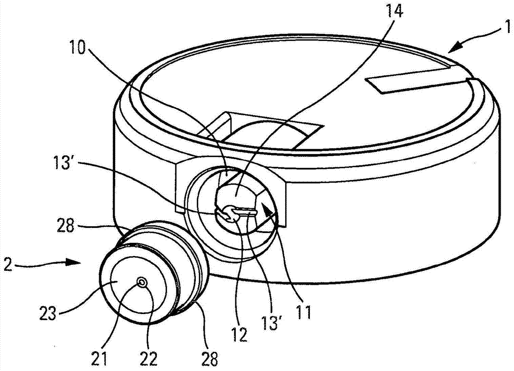
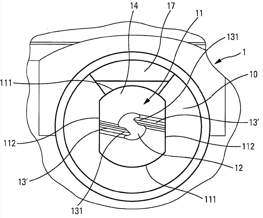
technical field [0001] The invention relates to a spray head for a fluid product, which comprises a spray hole defining a distribution axis, a swirl chamber and a swirl channel located upstream of the spray hole, the swirl chamber is bounded by an inner wall, the swirl channel Channel outlets are respectively defined, said channel outlets opening into the swirl chamber at the inner wall transversely to the dispensing axis to generate a swirl inside the swirl chamber, each swirl channel defining a spray axis extending from the channel outlet into the vortex chamber. Such spray heads may eg be in the form of buttons actuatable by means of one or several fingers of the hand. Preferred fields of application of the invention are the fields of perfumery, cosmetics or pharmaceuticals, without excluding other fields. Background technique [0002] In the state of the art, patent document FR-2399282 is known, which describes a common spray head comprising a dispensing orifice, a swi...

Claims


Application Information

Patent Timeline
IPC IPC(8): B05B1/34
CPCB05B1/341B05B1/3442B05B1/3431B05B7/04B05B1/3033B05B1/3436B05B1/3405B65D83/20B05B11/1011B05B9/0403
Inventor F·普利奥德
Owner APTAR FRANCE SAS
Learn More