
Accumulation-type gas supply device

一种气体供给、气体供给单元的技术,应用在流体压力致动装置、阀装置、运输和包装等方向,能够解决不能应对气体供给线路数设置空间、削减、小型化困难等问题,达到置换性提高、实现占地面积、时间缩短的效果

Inactive Publication Date: 2015-06-24
FUJIKIN INC
View PDF6 Cites 3 Cited by
  • Summary
  • Abstract
  • Description
  • Claims
  • Application Information

AI Technical Summary

Problems solved by technology

[0015] The present invention is to solve the above-mentioned problems in the conventional integrated gas supply device, that is, a) In the conventional gas supply device, the inlet on-off valve and the three-way on-off valve for purification are connected in a row (in series). In a device with a structure in which a plurality of gas supply lines S are arranged and fixed in parallel on the base plate, such as flow controllers, outlet on-off valves, etc., it is difficult to reduce the size of the device, and it cannot cope with the increase in the number of gas supply lines. increase and reduction of installation space; b) it is difficult to reduce the internal fluid passage volume of the integrated gas supply device to improve the replacement of gas, etc., to provide the following integrated gas supply device: through the flow controller Its own structure and the combined structure of multiple flow supply lines are improved, so that, for example, in an integrated gas supply device with 16 gas supply lines, the overall dimensions of the device are W=240mm, L=270mm, and L=270mm. H=240mm or less, and by realizing a large reduction in the volume of the gas passage inside the gas supply device, the volume of the clean room is reduced and the gas replacement performance is greatly improved, and even if it is installed on the top of a semiconductor manufacturing device, etc., It is also easy to perform maintenance and inspection, and can realize high-precision flow control and stable supply of clean gas, etc.

Method used


Image

  • Accumulation-type gas supply device
  • Accumulation-type gas supply device
  • Accumulation-type gas supply device

Examples


no. 1 Embodiment approach ]

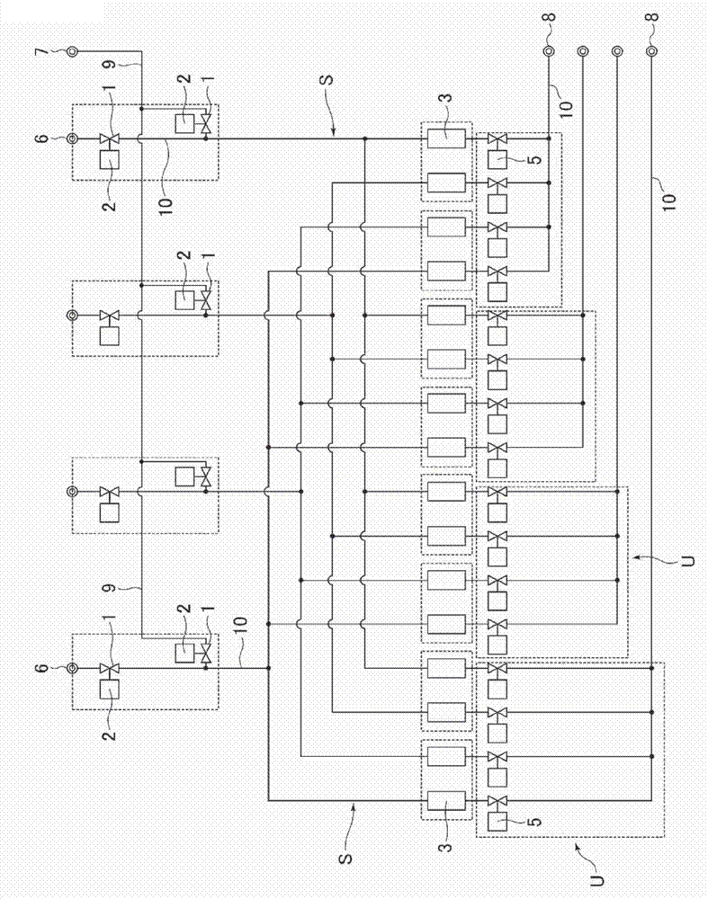
[0050] Figure 1 to Figure 7 is a diagram showing an integrated gas supply device for a semiconductor manufacturing apparatus according to a first embodiment of the present invention. In this first embodiment, as figure 1 As shown in the diagram of the gas supply system, the four gas types supplied to the processing gas inlet joint 6 pass through 16 gas supply lines S and one of the four processing gas passages 10, and then flow from the processing gas outlet joint 8 to the processing device ( omitting the illustration) supply.

[0051] That is, in the present embodiment, a total of 16 gas supply lines S are divided into four groups, the gas flowing in from each processing gas inlet joint 6 is introduced into the four groups, and the four groups are led out from each of the four groups. The gas supply lines S of the four systems are merged into one, and are supplied from the processing gas passage 10 to processing devices (not shown in the figure).

[0052] In addition, in ...

no. 1 example )

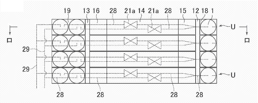
[0060] Figure 4 It is a diagram showing the structure of the gas supply unit U used in the first example. The gas supply unit U of the first example is formed by making the first unit body U of the same structure 1 and the second unit U 2 The gas inlet side block 12 and the gas outlet side block 13 arranged vertically parallel to each other and assembled to the front side and the back side of the gas inlet side block 12 and the gas outlet side block 13 are horizontally opposed.

[0061] That is, the first unit body U 1 It consists of a square main body block 18 for the inlet on-off valve, a square main body block 19 for the outlet on-off valve, a flow controller 3, an inlet on-off valve 1 and two outlet on-off valves 5, etc., and the inlet on-off valve The main body block 18 is airtightly fixed on the right side of the gas inlet side block 12, and the outlet opening and closing valve is airtightly fixed on the left side of the gas outlet side block 13 with the main body blo...

no. 2 example )

[0080] Image 6 It is a diagram showing a second example of the pressure type flow controller 3 used in the first embodiment of the present invention, and differs from the first example only in that a pressure detector 4 a is provided in addition to the pressure detector 4 .

[0081] By providing the pressure detector 4a to detect the pressure on the upstream side and the downstream side of the orifice 27, the flow rate can be controlled with high precision even in a non-critical state gas flow.

[0082] In addition, since the pressure detector 4a itself of the second example is well known, its description is omitted here.


PUM


Abstract

The purpose of the present invention is to increase the number of gas supply lines in an accumulation-type gas supply device for a semiconductor manufacturing apparatus, to reduce the size of the device, and to reduce the internal volume of the gas channels inside the device while enhancing the gas replacement properties of the device, minimizing installation space, and making various equipment easier to maintain. Two flow control devices (3) provided with a plurality of flow controllers are secured in a mutually opposed combination to a gas-inlet-side block (12) and a gas-outlet-side block (13) set apart from one another as viewed from above, and the flow control devices (3) are provided with an inlet opening / closing valve (1) and an outlet opening / closing valve (5), whereby a gas supply unit (U) provided with at least four gas supply lines (S) is formed, and a plurality of the gas supply units (U) are secured in a stacked configuration.

Description

technical field [0001] The present invention relates to an improvement of an integrated gas supply device, and relates to an integrated gas supply device capable of increasing the number of gas supply lines, reducing the size of the integrated gas supply device, facilitating maintenance and inspection, and improving gas replacement properties. Background technique [0002] Conventionally, a so-called integrated gas supply device is used to supply processing gas to semiconductor manufacturing equipment and the like. [0003] Figure 15 It is a figure showing an example, and the two-way on-off valves 41A, 41B, the three-way on-off valves 42A, 42B, the flow control device 43, etc. are passed through blocks 44, 45, 46, 47, 48 provided with gas flow paths. Integrate in series to form one gas supply line, and arrange and fix the gas supply line in parallel in multiple rows via blocks 45 and 49 to form an integrated gas supply device (Japanese Patent Application Laid-Open No. 5-172...

Claims


Application Information

Patent Timeline
Patent Type & Authority Applications(China)
IPC IPC(8): G05D7/00F16K27/00
CPCF16K27/003G05D7/0652Y10T137/87249Y10T137/87885F15B13/044G05D7/00G05D7/0682
Inventor 小艾睦典广濑隆山路道雄松田隆博
Owner FUJIKIN INC
Learn More