
Electromagnetic positioning and navigation device for transcranial magnetic stimulator

A technology of transcranial magnetic stimulation and electromagnetic positioning, applied in magnetic therapy, electrotherapy, treatment and other directions, can solve the problems of increasing stimulation intensity, increasing coil distance, energy waste, etc., to achieve the effect of verifying accuracy and reducing complexity

Active Publication Date: 2015-07-01
INST OF ELECTRICAL ENG CHINESE ACAD OF SCI
View PDF5 Cites 32 Cited by
  • Summary
  • Abstract
  • Description
  • Claims
  • Application Information

AI Technical Summary

Problems solved by technology

The machine vision positioning and navigation system requires a positioning cap. The thickness of the positioning cap increases the distance between the coil and the cerebral cortex, increases the stimulation intensity, and causes a waste of energy, especially when transcranial magnetic stimulation and EEG recording are required at the same time. Positioning caps and EEG electrode caps will increase the distance between the coil and the cerebral cortex
In the optical positioning and navigation system, due to the obstruction of light by objects, high requirements are placed on the positions of optical sensors and light sources, which also limits the use of optical positioning systems to a certain extent.
Secondly, the existing navigation system does not display the distribution of the induced electric field on the head in real time, especially the direction information of the induced electric field

Method used


Image

  • Electromagnetic positioning and navigation device for transcranial magnetic stimulator
  • Electromagnetic positioning and navigation device for transcranial magnetic stimulator
  • Electromagnetic positioning and navigation device for transcranial magnetic stimulator

Examples


Embodiment Construction

[0034] The present invention will be described in further detail below in conjunction with the accompanying drawings and specific embodiments.

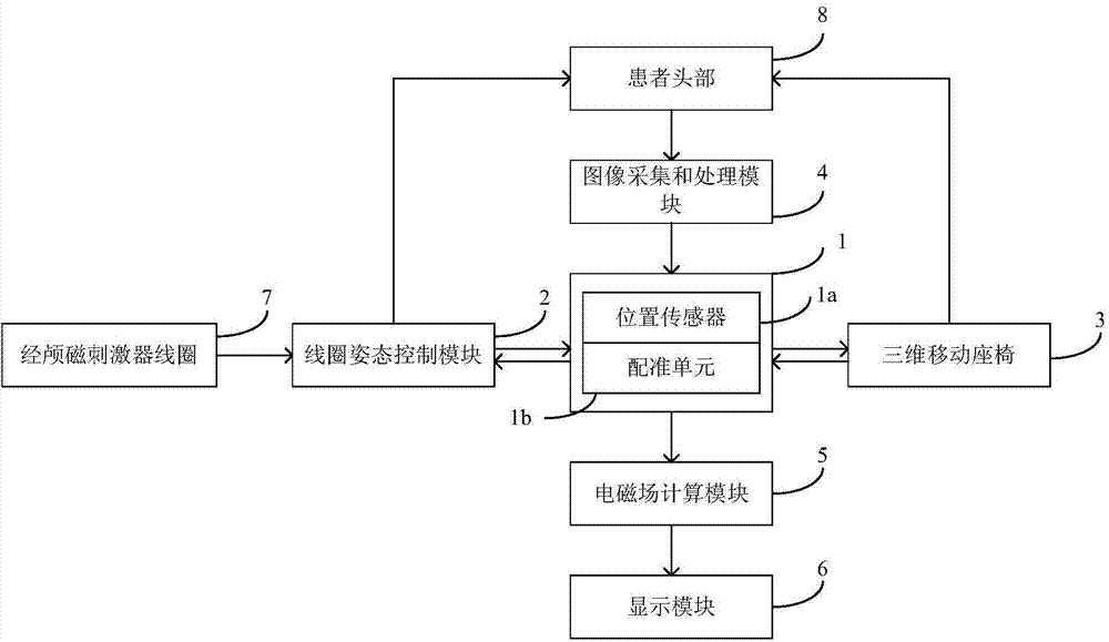
[0035] figure 1 Shown is an embodiment of the electromagnetic positioning and navigation device used in the transcranial magnetic stimulator of the present invention, and the described positioning and navigation device consists of an electromagnetic positioning and navigation module 1, a coil attitude control module 2, a three-dimensional mobile seat 3, image acquisition and It consists of a processing module 4, an electromagnetic field calculation module 5, a display module 6 and a transcranial magnetic stimulator coil 7.

[0036] The electromagnetic positioning and navigation module 1 includes a position sensor 1a and a registration unit 1b.

[0037] The electromagnetic positioning and navigation module 1 is connected to the coil attitude control module 2 , the three-dimensional mobile seat 3 , the image acquisition and processing ...


PUM


Abstract

An electromagnetic positioning and navigation device for a transcranial magnetic stimulator is composed of an electromagnetic positioning and navigation module (1), a coil gesture control module (2), a three-dimensional seat (3), an image collection and processing module (4), an electromagnetic calculation module (5), a display module (6) and a transcranial magnetic stimulator coil (7). The electromagnetic positioning and navigation module (1) is connected with the coil gesture control module (2) and the three-dimensional seat (3), and the coil gesture control module (2) is installed on the transcranial magnetic stimulator coil (7). The image collection and processing module (4) can rebuild a three-dimensional head model of a patient in the image space to mark therapeutic targets. The electromagnetic positioning and navigation module (1) records space position and coil gesture of the head (8) of the patient and conducting alignment on head positions in the image space and the sensor space and the position of the transcranial magnetic stimulator coil (7). Induction field distribution of the head of the patient is displayed in the display module (6) by means of calculation of the electromagnetic calculation module (5).

Description

technical field [0001] The invention relates to a medical device, in particular to a positioning and navigation device for a magnetic stimulator. Background technique [0002] In the early 1980s, British scientists Baker and others began to study the use of magnetic stimulation to intervene in brain neural activity, and successfully stimulated the motor center of the human brain for the first time in 1985, and measured the motor cortical evoked potential (Motor- evoked potentials, MEPs). This also marks the entry of Transcranial Magnetic Stimulation (TMS) into the stage of history. With the development of high-power devices and the improvement of circuits, repetitive magnetic stimulators (Repetitive Transcranial Magnetic Stimulation, rTMS) appeared in the late 1980s, which can generate 1–100 pulses per second. According to the principle of electromagnetic induction, the magnetic stimulator releases the energy stored in the capacitor into the stimulating coil in a short tim...

Claims


Application Information

Patent Timeline
Patent Type & Authority Applications(China)
IPC IPC(8): A61N2/04
Inventor 张广浩霍小林吴昌哲张丞
Owner INST OF ELECTRICAL ENG CHINESE ACAD OF SCI
Learn More