Hot extrusion die with improved lower die choke flow structure

A hot extrusion die and structural improvement technology, applied in the direction of metal extrusion die, etc., can solve the problems of product cracking and damage, affecting product strength, small material flow, etc. high effect

Inactive Publication Date: 2015-07-01
捷安特轻合金科技(昆山)股份有限公司
View PDF5 Cites 2 Cited by
  • Summary
  • Abstract
  • Description
  • Claims
  • Application Information

AI Technical Summary

Problems solved by technology

[0002] All kinds of profiles are formed by hot extrusion dies. Generally, hot extrusion dies are composed of an upper die and a lower die. The upper die is equipped with a guide plate and a core head. The diversion hole between the bridges enters the mold after diversion, then flows into the welding chamber, and then converges after entering the welding chamber, and then enters the molding space formed by the core head and the forming hole for extrusion molding, and finally from the discharge At present, the bottom surface of the common welding chamber is a circular plane structure. The material enters the welding chamber along the diversion hole, and the material enters the forming hole after converging in the welding chamber. The flow of materials in the welding chamber is small, and it is difficult to weld the materials in each split hole well, and the surface of the formed product will produce a linear welding line along its length, which will affect the strength of the product. Prone to cracking and damage during use

Method used


Image

  • Hot extrusion die with improved lower die choke flow structure
  • Hot extrusion die with improved lower die choke flow structure
  • Hot extrusion die with improved lower die choke flow structure

Examples


Embodiment

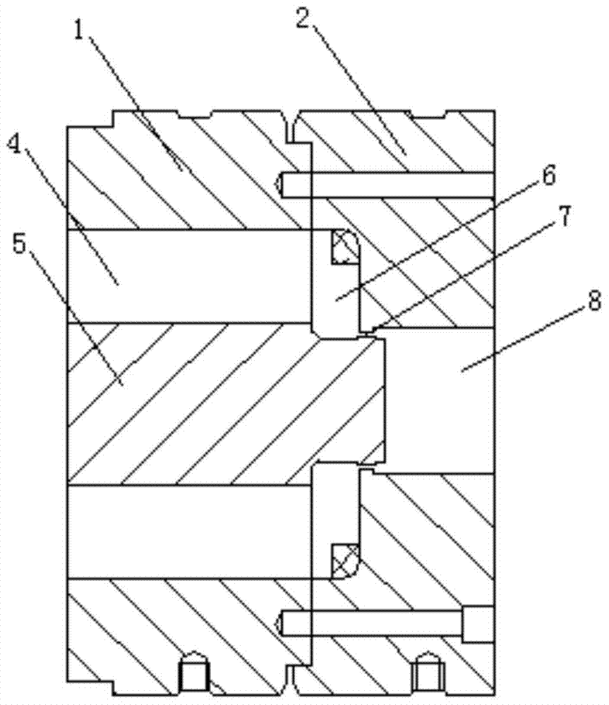
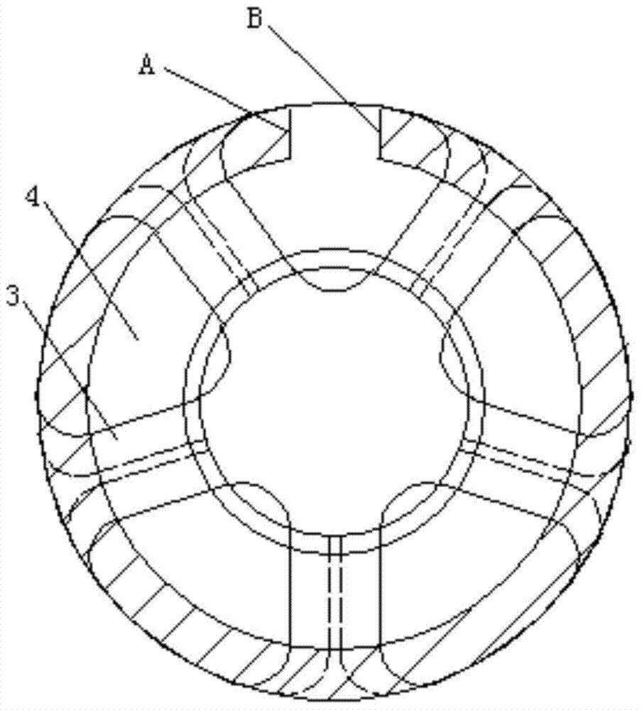
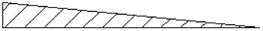
[0012] Embodiment: A hot extrusion die with an improved flow resistance structure of the lower die, including an upper die 1 and a lower die 2 that can be superimposed and connected together. There are a number of bridge positions 3, and split holes 4 are formed between each bridge position. The discharge end of the upper die 1 is provided with a core head 5, and the lower die 2 is sequentially provided with connected welding chambers 6, The forming hole 7 and the discharge hole 8, the welding chamber 6 communicates with the split hole 4 of the upper mold 1, the core head 5 of the upper mold 1 is inserted in the forming hole 7 of the lower mold 2, and the lower mold 2 is welded The bottom surface of the welding chamber 6 is provided with a circle of spiral structure whose axial height gradually decreases. By setting the spiral structure on the inner bottom surface of the welding chamber 6, the material entering the welding chamber 6 from the split hole 4 is rotated at a high sp...


PUM


Abstract

The invention discloses a hot extrusion die with an improved lower die choke flow structure. The hot extrusion die comprises an upper die and a lower die, which can be superposed and connected together back and forth, wherein a flow guide plate is arranged at a feeding end of the upper die; a plurality of bridge sites are arranged on the flow guide plate; tap holes are formed among the bridge sites; a core head is arranged at a discharge end of the upper die; a welding chamber, a molding hole and a discharge hole, which are communicated with one another, are sequentially formed in the lower die from the feeding end to the discharge end; the welding chamber is communicated with the tap hole of the upper mold; the core head of the upper mold is inserted into a molding hole of the lower mold; and a circle of spiral structure of which the axial height is gradually reduced is arranged on the bottom surface of the welding chamber of the lower mold. Welding lines on the surface of the product which is molded from the material disclosed by the invention by the molding hole are slight or even disappear; the slight welding lines also extend in a spiral curve manner; the hot extrusion die is high in overall strength, and is not easily fractured or damaged when being subjected to bending, cold drawing and stretching; and the product is high in surface accuracy and small in dimension error.

Description

technical field [0001] The invention relates to an extrusion die, in particular to a hot extrusion die with an improved flow resistance structure of a lower die. Background technique [0002] All kinds of profiles are formed by hot extrusion dies. Generally, hot extrusion dies are composed of an upper die and a lower die. The upper die is equipped with a guide plate and a core head. The diversion hole between the bridges enters the mold after diversion, then flows into the welding chamber, and then converges after entering the welding chamber, and then enters the molding space formed by the core head and the forming hole for extrusion molding, and finally from the discharge At present, the bottom surface of the common welding chamber is a circular plane structure. The material enters the welding chamber along the diversion hole, and the material enters the forming hole after converging in the welding chamber. The flow of materials in the welding chamber is small, and it is ...

Claims


Application Information

Patent Timeline
Patent Type & Authority Applications(China)
IPC IPC(8): B21C25/02
CPCB21C25/02
Inventor 涂季冰李展志吕传锋高爱林
Owner 捷安特轻合金科技(昆山)股份有限公司
Why Eureka
Try Eureka