Applicable to slab-beam bridge slab transportation and installation vehicle

A bridge deck and installation vehicle technology, which is applied to bridges, bridge construction, erection/assembly of bridges, etc., can solve the problems of insufficient safety and stability of posts, consume a lot of time and manpower, and increase erection costs, so as to reduce transportation and erection costs , Convenient suspension installation, stable structure and performance

Active Publication Date: 2016-08-31
GUANGDONG PROVINCIAL CHANGDA HIGHWAY ENG +1
View PDF5 Cites 0 Cited by
  • Summary
  • Abstract
  • Description
  • Claims
  • Application Information

AI Technical Summary

Problems solved by technology

In the prior art, the installation method of bridge prefabricated panels has a self-propelled crane frame to try to install them in place, that is, directly hoist the prefabricated panels to the installation position with a crane. This method requires large-scale lifting and transportation equipment and a construction site. Within the range of the working radius and working height of the heavy arm, there must be no transmission lines and other obstacles, and it is not suitable for use under the conditions of space and plane size restrictions. In addition, because there is usually water under the bridge, a hoist can be used to cooperate with the chain guide frame. , set up temporary supports at both ends of the bridge body, and lay two-way tracks longitudinally on the outside of the bridge body. The hoist at one end of the bridge is fixed at the bridge head, and the hoist at the other end is respectively fixed and movable on each pier. The beam is moved longitudinally by the hoist and manually The hoist and steel pipe move the beam horizontally, and install the prefabricated panels in sequence. This method is complicated to operate, requires a lot of time, manpower, and a lot of money, and the safety and stability of the post during the hoisting process is insufficient.
Moreover, in order to ensure the overall force balance of the bridge during installation, the bridge prefabricated panels need to be laid symmetrically from the middle of the bridge to both ends. In view of this requirement, the above two methods have the problems of complicated operation and inconvenient movement, and both of the above two methods need to be installed on the bridge. Erection of equipment on the outside of the body greatly increases the cost of erection

Method used


Image

  • Applicable to slab-beam bridge slab transportation and installation vehicle
  • Applicable to slab-beam bridge slab transportation and installation vehicle
  • Applicable to slab-beam bridge slab transportation and installation vehicle

Examples


Embodiment Construction

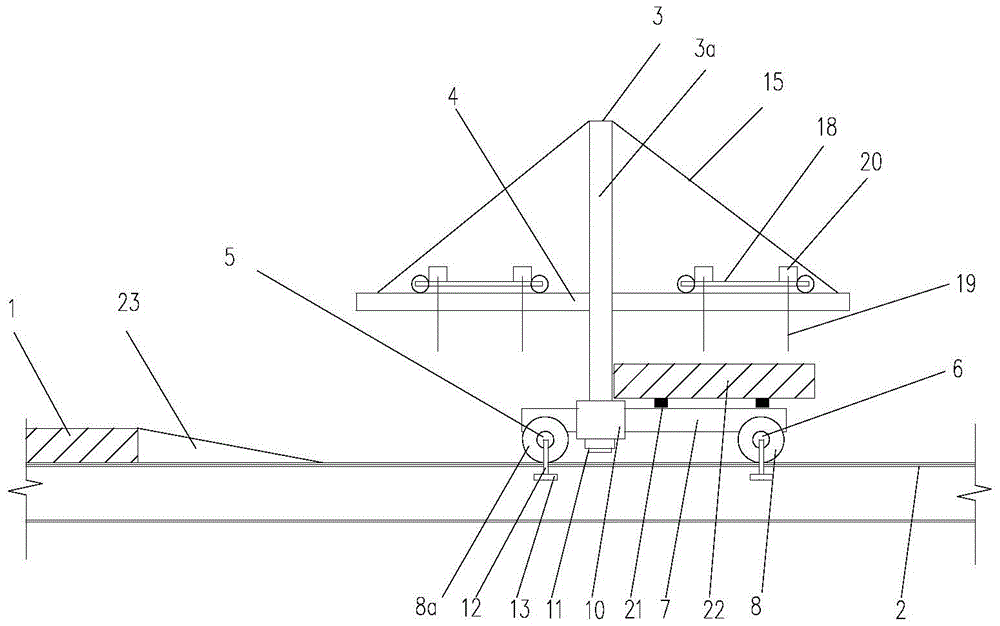
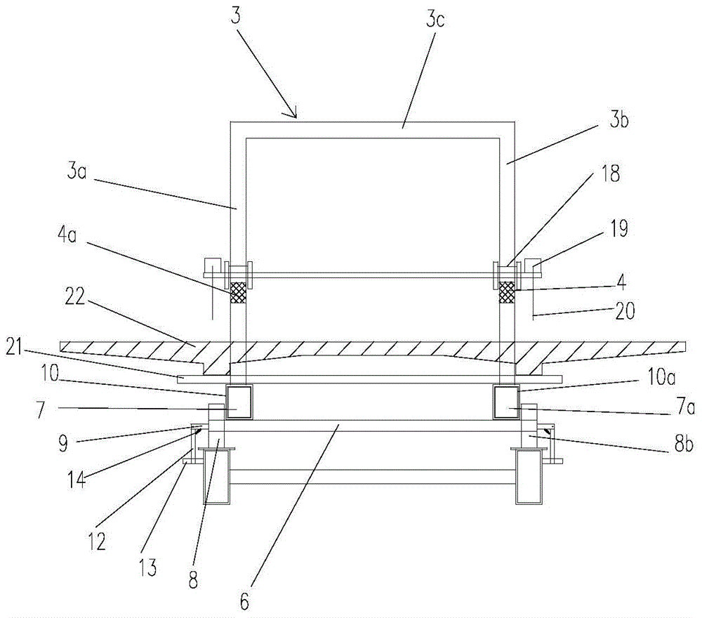
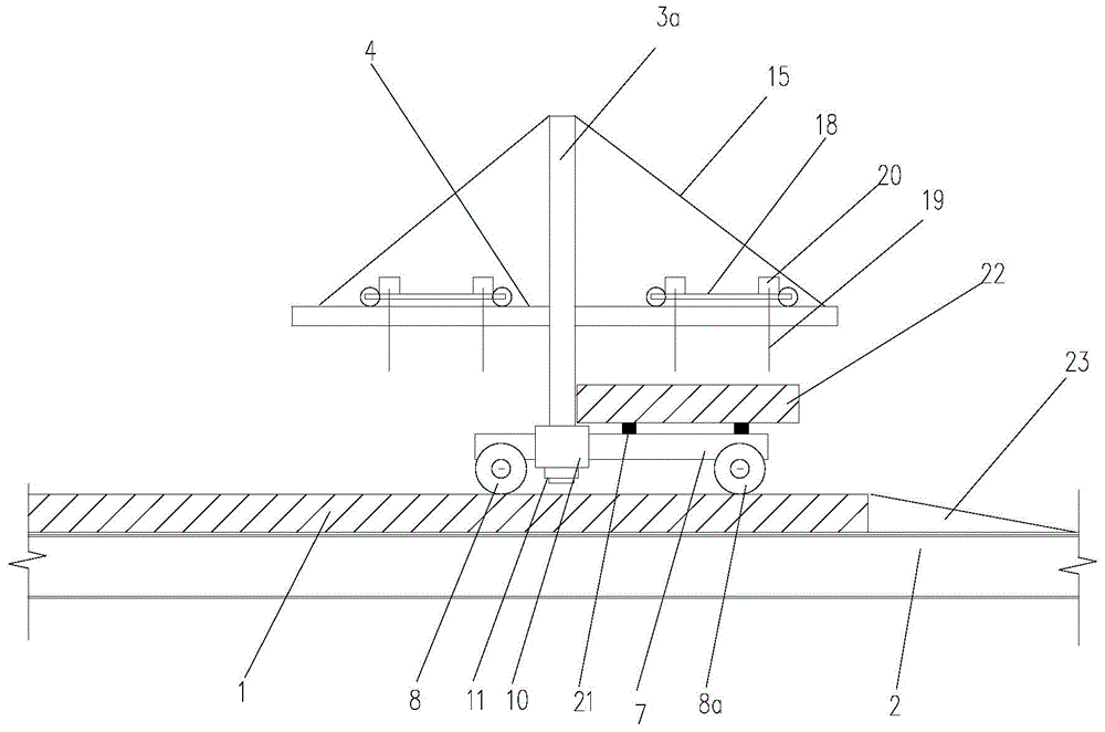
[0026] figure 1 It is a schematic diagram of the state structure when the transport and installation vehicle of the present invention walks on the steel truss beam, figure 2 for figure 1 Schematic diagram of the right side view, image 3 Schematic diagram of the state structure when the transport and installation vehicle walks on the laid bridge slab, Figure 4 for image 3 Schematic diagram of the right side view, Figure 5 It is a schematic diagram of the state structure of the transport and installation vehicle of the present invention when the bridge deck is installed, Image 6 for Figure 5 Schematic cross-sectional view from the right side: the transport and installation vehicle for slab-beam bridge slabs in this embodiment includes an installation component and a walking component that is arranged in cooperation with the installation component and can walk longitudinally along the upper chord of the bridge slab 1 and truss 2 that have been laid;

[0027] The inst...


PUM


Abstract

The invention discloses a carriageway slab transportation and installation vehicle capable of traveling on a slab and beam. The carriageway slab transportation and installation vehicle comprises an installation component and a traveling component matched with the installation component and capable of longitudinally traveling along the paved carriageway slab and the upper string of a truss. The traveling component can travel on the steel truss beam, a horizontal spacing component arranged on the axial extension section of a front axle and a rear axle can ensure that traveling wheels travel longitudinally along truss girders without crosswise deviation, and the horizontal spacing component can be vertically overturned to be horizontally supported, so that the transportation and installation vehicle can travel to the carriageway slab from the steel truss beam without formation of obstruction and can bear the carriageway slab to be paved to travel freely to reach a designated installation position of the carriageway slab on the truss of a bridge and the paved carriageway slab, carriageway slab erection equipment does not need to be arranged on the outer side of a bridge body, and erection cost is greatly lowered.

Description

technical field [0001] The invention relates to the field of bridge engineering, in particular to a bridge road slab transportation and installation vehicle applicable to slab-beams. Background technique [0002] In highway and bridge engineering, prefabricated slabs have been widely used as bridge slabs due to their ease of use. In the prior art, the installation method of bridge prefabricated panels has a self-propelled crane frame to try to install them in place, that is, directly hoist the prefabricated panels to the installation position with a crane. This method requires large-scale lifting and transportation equipment and a construction site. Within the range of the working radius and working height of the heavy arm, there must be no transmission lines and other obstacles, and it is not suitable for use under the conditions of space and plane size restrictions. In addition, because there is usually water under the bridge, a hoist can be used to cooperate with the chai...

Claims


Application Information

Patent Timeline
Patent Type & Authority Patents(China)
IPC IPC(8): E01D21/00
CPCE01D21/00
Inventor 王中文周志祥高燕梅
Owner GUANGDONG PROVINCIAL CHANGDA HIGHWAY ENG
Why Eureka
Try Eureka