
Novel helicopter water-cooled engine cooling system

A water-cooled engine and heat dissipation system technology, which is applied in the aviation field, can solve the problems of power consumption of helicopters, space occupied by the heat dissipation system, and low heat dissipation efficiency.

Inactive Publication Date: 2015-07-01
北京海空行科技有限公司
View PDF5 Cites 4 Cited by
  • Summary
  • Abstract
  • Description
  • Claims
  • Application Information

AI Technical Summary

Problems solved by technology

[0005] In order to overcome the shortcomings of the above-mentioned prior art, the present invention provides a novel helicopter water-cooled engine heat dissipation system to solve the problem that the conventional helicopter water-cooled heat dissipation system needs to use an electronic fan to dissipate heat, the system is complicated, and at the same time, it needs to consume precious electric energy on the helicopter to dissipate heat. Low efficiency, cooling system takes up valuable body space and other disadvantages
[0007] Compared with the prior art, the beneficial effect of the present invention is to solve the problem that the conventional helicopter water-cooling heat dissipation system needs to be dissipated by means of an electronic fan, the system is complicated, and at the same time, it needs to consume precious electric energy on the helicopter, the heat dissipation efficiency is low, and the heat dissipation system takes up valuable airframe. Disadvantages such as space

Method used


Image

  • Novel helicopter water-cooled engine cooling system
  • Novel helicopter water-cooled engine cooling system
  • Novel helicopter water-cooled engine cooling system

Examples


Embodiment Construction

[0023] The present invention will be further described below in conjunction with the accompanying drawings.

[0024] In order to overcome the shortcomings of the above-mentioned prior art, the present invention provides a novel helicopter water-cooled engine heat dissipation system to solve the problem that the conventional helicopter water-cooled heat dissipation system needs to use an electronic fan to dissipate heat, the system is complicated, and at the same time, it needs to consume precious electric energy on the helicopter to dissipate heat. The efficiency is low, and the heat dissipation system takes up valuable body space and other disadvantages.

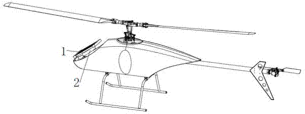
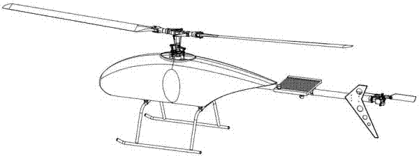
[0025] see Figure 6 , the overall layout of the helicopter water-cooled engine cooling system related to this embodiment is as follows:

[0026] The main rotor system 1 is located at the top of the system, and its downwash flow provides a cooling source for the new helicopter water-cooled engine cooling system.

[0027] ...


PUM


Abstract

The invention discloses a novel helicopter water-cooled engine cooling system. The helicopter novel water-cooled engine cooling system mainly comprises a main rotor system, an engine, an engine water outlet pipe, a radiator, an expansion box (provided with a water filling port), an overflow bottle, an engine water inlet pipe and the like. The novel helicopter water-cooled engine cooling system mainly solves the problems that a conventional helicopter water-cooled cooling system conducts heat dissipation by means of an electronic fan, is complex in system and needs to consume precious electric energy on a helicopter, the cooling efficiency is low, and the cooling system occupies precious engine space. According to the novel helicopter water-cooled engine cooling system, helicopter rotor downwash serves as a cooling source, an electronic fan is not needed, the whole helicopter mechanical and circuit structure is simplified, the structural weight is reduced, the electric energy and the loading space on the helicopter are saved, the environmental adaptation is enhanced, and the cooling efficiency is improved. The calculation result of the induced velocity distribution of the downwash 0.2R below a rotor disk is shown in the Figure 3. Since the wake shrinks and a calculation point at the radius of the rotor disk is located outside the wake, an upward induced velocity exists. According to the induced velocity distribution, the calculation result is reasonable and credible; the induced velocity is maximized at 0.7R.

Description

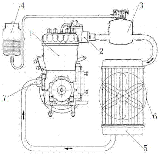
technical field [0001] The invention relates to the field of aviation technology, in particular to a novel helicopter water-cooled engine cooling system. Background technique [0002] At present, the conventional form helicopter water-cooled engine cooling system includes: engine, engine outlet pipe, expansion tank (water filling port), overflow bottle, radiator, electronic fan and engine water inlet pipe. The working principle of the conventional helicopter water-cooled engine cooling system is as follows: figure 1 When the engine is working, the temperature rises and the cooling water of the cylinder block is discharged from the engine outlet pipe under the drive of the engine water pump, and enters the radiator through the expansion tank (water inlet); the radiator is equipped with an electronic fan, which is controlled by a temperature control switch , when the temperature exceeds a certain value, the temperature control switch is turned on, the electronic fan works, an...

Claims


Application Information

Patent Timeline
Patent Type & Authority Applications(China)
IPC IPC(8): F01P3/00
Inventor 王强陈铭王祥祥王放胡奉言曹飞张兴文马艺敏王保兵张猛孙然李梁武梅丽文刘永辉徐安安
Owner 北京海空行科技有限公司
Learn More