Engine cooling fan control method and system and engine cooling system

A cooling fan and control method technology, applied in the direction of engine cooling, combustion engine, engine components, etc., can solve the problems that it is difficult to ensure that the engine works in the best state, and achieve the effect of improving life, fuel saving and adaptability

Pending Publication Date: 2022-03-15
ZHENGZHOU YUTONG BUS CO LTD
View PDF7 Cites 3 Cited by
  • Summary
  • Abstract
  • Description
  • Claims
  • Application Information

AI Technical Summary

Problems solved by technology

[0005] The object of the present invention is to provide a control method, system and engine cooling system for an engine cooling fan, so as to solve the problem that the existing engine cooling system is difficult to ensure that the engine works in an optimal state

Method used


Image

  • Engine cooling fan control method and system and engine cooling system
  • Engine cooling fan control method and system and engine cooling system
  • Engine cooling fan control method and system and engine cooling system

Examples


Embodiment 1

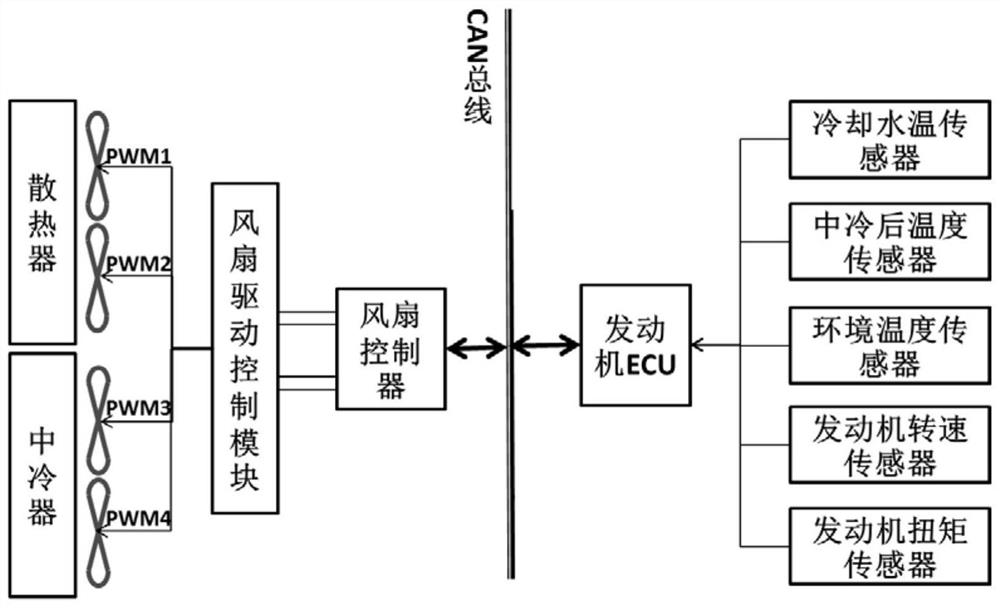
[0028] Such as figure 2 As shown, the engine cooling system adopts a parallel arrangement, that is, the radiator and the intercooler are arranged side by side, and two sets of electronic fans are used to independently cool the radiator and the intercooler.

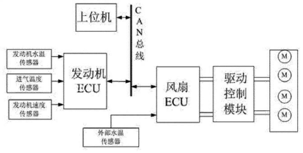
[0029] The engine cooling system includes a fan controller, CAN bus and engine ECU. The engine ECU is connected with a cooling water temperature sensor, an intercooler temperature sensor, an ambient temperature sensor, an engine speed sensor and an engine torque sensor. The engine collects the engine water outlet temperature through the above sensors. , intake air temperature after intercooling, ambient temperature, engine speed and engine torque signals, and output to the CAN bus. The input end of the fan controller is provided with a CAN communication interface. Through the CAN communication interface, the fan controller can obtain the signals uploaded by the engine ECU to the CAN bus. The signals include: ambient tempe...

Embodiment 2

[0052] The difference between this embodiment and the engine cooling system embodiment 1 is that the engine cooling system of this embodiment also includes a GPS module and a vehicle-mounted networking data terminal, such as Figure 5 As shown, the function of the GPS module is to collect the location information of the vehicle and send the vehicle location information to the CAN bus; the vehicle network data terminal reads the location information of the vehicle through the CAN bus, and combines the 3D map information sent through the cloud, Identify the slope information of the vehicle currently and about to enter the road, and send the slope information to the CAN bus.

[0053] Moreover, the engine cooling fan control method of the present embodiment also includes the following steps:

[0054] Obtain slope information and judge whether the slope of the road ahead is ≥7°; if so, the fan controller drives the radiator fan and the intercooler fan to run at full speed until the...


PUM


Abstract

The invention relates to an engine cooling fan control method and system and an engine cooling system, and belongs to the technical field of engine heat management. The method comprises the following steps: 1) acquiring current environment temperature information and engine load state information; (2) the environment temperature grade of the current environment temperature is judged; judging the engine load state grade to which the current engine load state belongs; 3) matching a corresponding fan control interval according to the corresponding relationship among the environment temperature grade, the engine load state grade and the fan control interval; and 4) correspondingly adjusting the rotating speed of the radiator fan and/or correspondingly adjusting the rotating speed of the intercooler fan according to the set value of the matched fan control interval. The radiator fan and/or the intercooler fan can be correspondingly adjusted according to the current environment temperature and the load grade of the engine, the adaptability of the engine cooling system to the external environment and the vehicle load state can be improved, and it is guaranteed that the engine works in the optimal state.

Description

technical field [0001] The invention relates to an engine cooling fan control method, system and engine cooling system, belonging to the technical field of engine thermal management. Background technique [0002] The vehicle cooling system is mainly used to maintain the engine water temperature and intake air temperature in the optimal range, so as to ensure the optimal engine efficiency. The main function of the fan in the system is to force the external air to flow through the heat exchanger core and perform forced heat exchange. In this way, the waste heat of the engine and other systems can be dissipated to the external environment in time. Traditional vehicle cooling fans are generally directly driven by the engine, and the fan speed is coupled with the engine speed, so the speed cannot be actively adjusted according to the actual heat dissipation requirements, which inevitably leads to excess cooling capacity and increased energy consumption of the cooling system. How...

Claims


Application Information

Patent Timeline
Patent Type & Authority Applications(China)
IPC IPC(8): F01P7/04F02B29/04
CPCF01P7/04F01P7/026F02B29/0493Y02T10/12
Inventor 王宏朝王警卫吕培科何青治郑辉刘积成
Owner ZHENGZHOU YUTONG BUS CO LTD
Why Eureka
Try Eureka