Water inputting and returning pipe joint of double-layer drill rod
A technology of double-layer drill pipe and water pipe joints, which is applied in the direction of pipes/pipe joints/fittings, pipes, pipe components, etc. It can solve the problems of time-consuming and labor-consuming, affect the progress of the project, and cumbersome procedures, so as to reduce procedures and save labor. , the effect of streamlining operations
- Summary
- Abstract
- Description
- Claims
- Application Information
AI Technical Summary
Problems solved by technology
Method used
Image

Examples
Embodiment Construction
[0024] The present invention will be further described in detail below in conjunction with the accompanying drawings and embodiments.
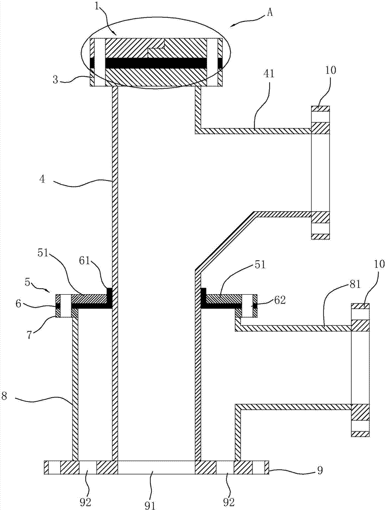
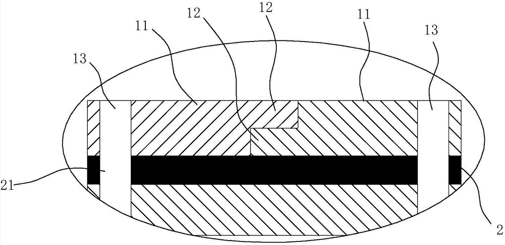
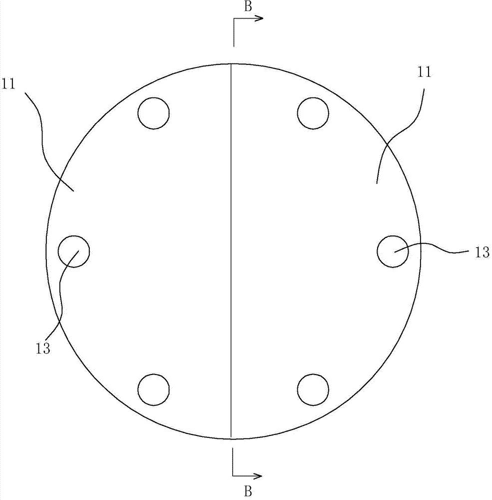
[0025] The inlet and outlet pipe joints of the double-deck drill pipe of the present embodiment, such as Figure 1 to Figure 5 As shown, it includes an inner tube 4 and an outer tube 8 sleeved on the inner tube 4, wherein the inner tube 4 is welded at the center of the outer tube 8, and the same side of the inner tube 4 and the outer tube 8 are respectively provided with a first joint 41 and a The second joint 81, the first joint 41 and the second joint 81 are respectively welded with connecting flanges 10 connected with water pipes. The top end of the inner tube 4 is a sealing connector 1 , a circular rubber sealing gasket 2 and a first fastening flange 3 welded together with the top end of the inner tube 4 from top to bottom. The sealing connector 1 is formed by cooperating and splicing two first connectors 11, each first connector 11 is sp...
PUM
 Abstract
Description
Claims
Application Information
PatSnap Eureka turns technology decisions into work you can execute. Powered by our Innovation Knowledge Graph, it runs expert workflows across engineering, life sciences, materials and intellectual property. Get your review-ready output in minutes.


