Petal type big flame cover and combustor provided with same

A technology of a large fire cover and a burner, which is applied to burners, gas fuel burners, combustion methods, etc., can solve the problems of a large amount of flue gas, waste of energy, energy waste, etc., and achieve full combustion of gas, improve safety, and improve thermal efficiency. Effect

Inactive Publication Date: 2015-07-01
SHANGHAI RINNAI +1
View PDF4 Cites 4 Cited by
  • Summary
  • Abstract
  • Description
  • Claims
  • Application Information

AI Technical Summary

Problems solved by technology

[0003] The fire holes on the existing large fire cover are generally distributed evenly along the circumference of the large fire cover, or distributed along the radial direction. When the burner burns, the fire from the fire holes will form a barrier, preventing the supply of secondary air, which is easy to cause Insufficient gas combustion, the thermal efficiency of the burner with such a large fire cover is generally not too high
Therefore, not only a lot of energy is wasted, but also the thermal efficiency of the burner is reduced
At the same time, when the fire holes are evenly distributed along the circumferential surface of the fire cover, the burning flame will easily burn to the pot frame, resulting in a large amount of smoke, which will adversely affect the health of the user
[0004] In addition, because the fire outlet is set on the outer ring of the fire cover, it is easy to cause uneven heating of the bottom of the pot. In order to achieve the same heating effect, not only the user needs to spend more time, but also consumes more gas resources, resulting in waste of energy
[0005] In the existing burner, the fire transfer groove is set on the surface of the fire cover, when liquid overflows in the pot, the liquid flowing out will block the fire transfer groove, which will easily cause ignition problems

Method used


Image

  • Petal type big flame cover and combustor provided with same
  • Petal type big flame cover and combustor provided with same
  • Petal type big flame cover and combustor provided with same

Examples


Embodiment 1

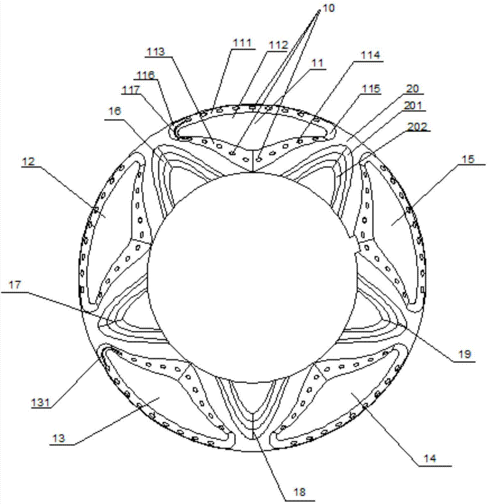
[0037] Such as figure 1 Shown, present embodiment proposes a kind of petal formula big fire cover. A plurality of fire holes 10 are disposed on the first side 111 , the second side 113 and the third side 114 . In this embodiment, the width of the fire cover is 25mm.

[0038] Such as figure 1 As shown, the upper surface of the fire cover 1 is provided with five bosses at intervals, which are respectively the first boss 11, the second boss 12, the third boss 13, the fourth boss 14 and the fifth boss 15, two A passage for supplementing secondary air is provided between adjacent bosses, that is, there is a gap between two adjacent bosses. Each channel for supplying secondary air is formed with concave platforms, which are respectively the first concave platform 16, the second concave platform 17, the third concave platform 18, the fourth concave platform 19 and the fifth concave platform 20. The platform and the concave platform are arranged at intervals in the manner of one c...


PUM


Abstract

The invention discloses a petal type big flame cover and a combustor provided with the same. The petal type big flame cover at least comprises an upper surface. A plurality of bosses are arranged on the upper surface at intervals. A channel for supplementing secondary air is formed between every two adjacent bosses. Each boss is provided with a first surface with the high exterior and the low interior, and a plurality of side faces, wherein the first surface inclines inwards, and flame outlet holes are formed in the first surface or the multiple side faces. A concave table is formed on the portion, close to one side of the center of the big flame cover, of each channel for supplementing the secondary air. The height of each concave table is smaller than the height of each boss. A flame conveying groove used for being connected with flames of an inner ring and an outer ring is formed in each boss. The petal type big flame cover has the advantages that the flame outlet holes are formed reasonably, flames are distributed uniformly, and the heat efficiency is high.

Description

technical field [0001] The invention relates to the technical field of burners, in particular to a petal-type fire cover and a burner equipped with a petal-type fire cover. Background technique [0002] Atmospheric burners commonly used now generally include a large fire cover, a small fire cover, a fire distributor and an injection part. Wherein, the upper surface of the large fire cover is generally a plane, or the center part is a plane, and the outer ring is inclined outward. When the burner of this plane structure has liquid overflowing in the pot, the liquid flowing out will block the fire hole, and then Reduce the effective number of fire outlets, and abnormal combustion occurs. [0003] The fire holes on the existing large fire cover are generally distributed evenly along the circumference of the large fire cover, or distributed along the radial direction. When the burner burns, the fire from the fire holes will form a barrier, preventing the supply of secondary air...

Claims


Application Information

Patent Timeline
Patent Type & Authority Applications(China)
IPC IPC(8): F23D14/46F23D14/04
CPCF23D14/46F23D14/02F23D14/58F23D14/64
Inventor 倪娟娟郭寿俊黄若瑾
Owner SHANGHAI RINNAI
Why Eureka
Try Eureka