Supercharge Your Innovation With Domain-Expert AI Agents!

Improved High Energy Ignition Spark Igniter

A spark igniter and spark technology, applied in the field of ignition systems, can solve problems such as difficulty in forming sparks and reduced output energy

Active Publication Date: 2017-06-23
JOHN ZINK CO LLC
View PDF7 Cites 0 Cited by
  • Summary
  • Abstract
  • Description
  • Claims
  • Application Information

AI Technical Summary

Problems solved by technology

[0006] Due to cost and size considerations, it is desirable to minimize the output energy of the HEI system, however, because the output energy is reduced, it will be more difficult to form a spark under unfavorable burner start-up conditions

Method used


Image

  • Improved High Energy Ignition Spark Igniter
  • Improved High Energy Ignition Spark Igniter
  • Improved High Energy Ignition Spark Igniter

Examples


Embodiment

[0058] The following examples are provided to illustrate the invention. This example is not intended and should not limit, modify or limit the scope of the present invention in any way.

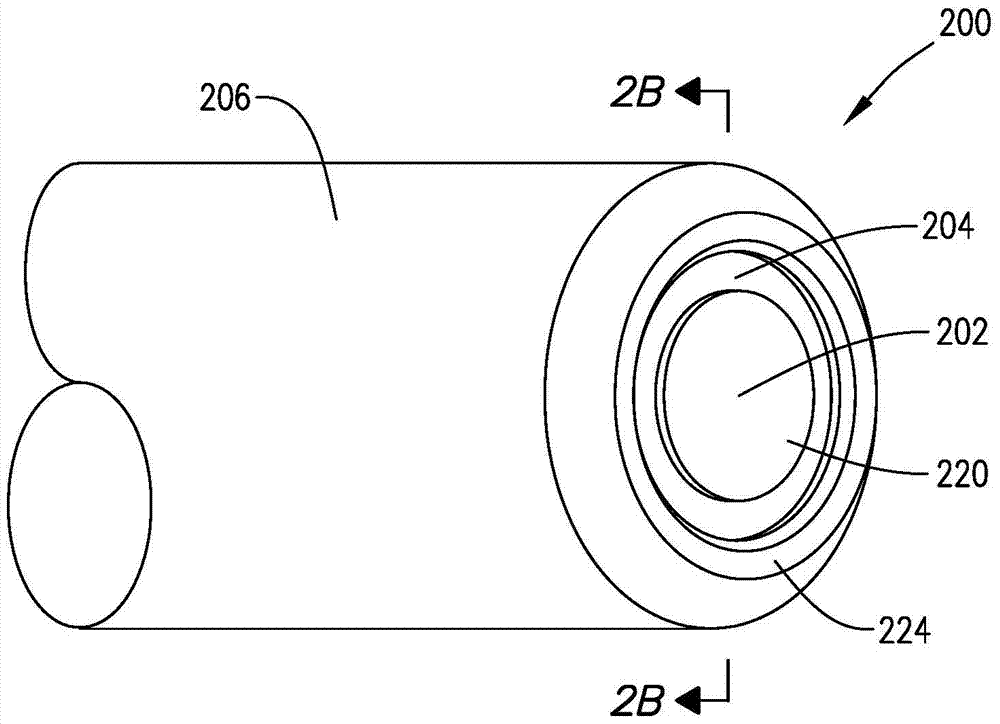
[0059] Two different ignition activators and five different igniter tip geometries were tested (see Tables 1 and 2 for details of the tests).

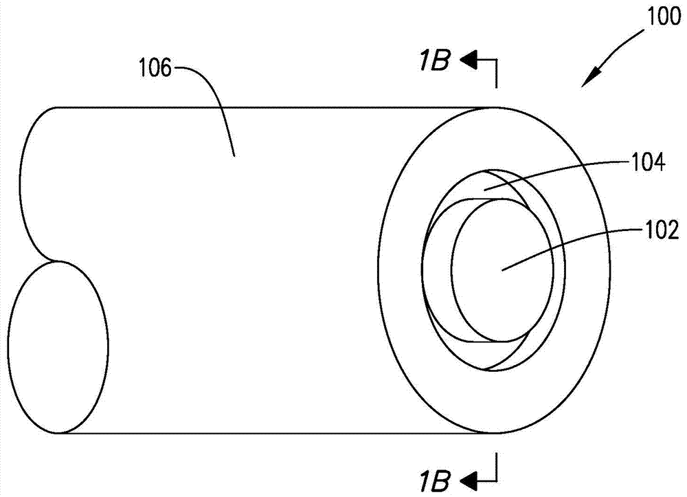
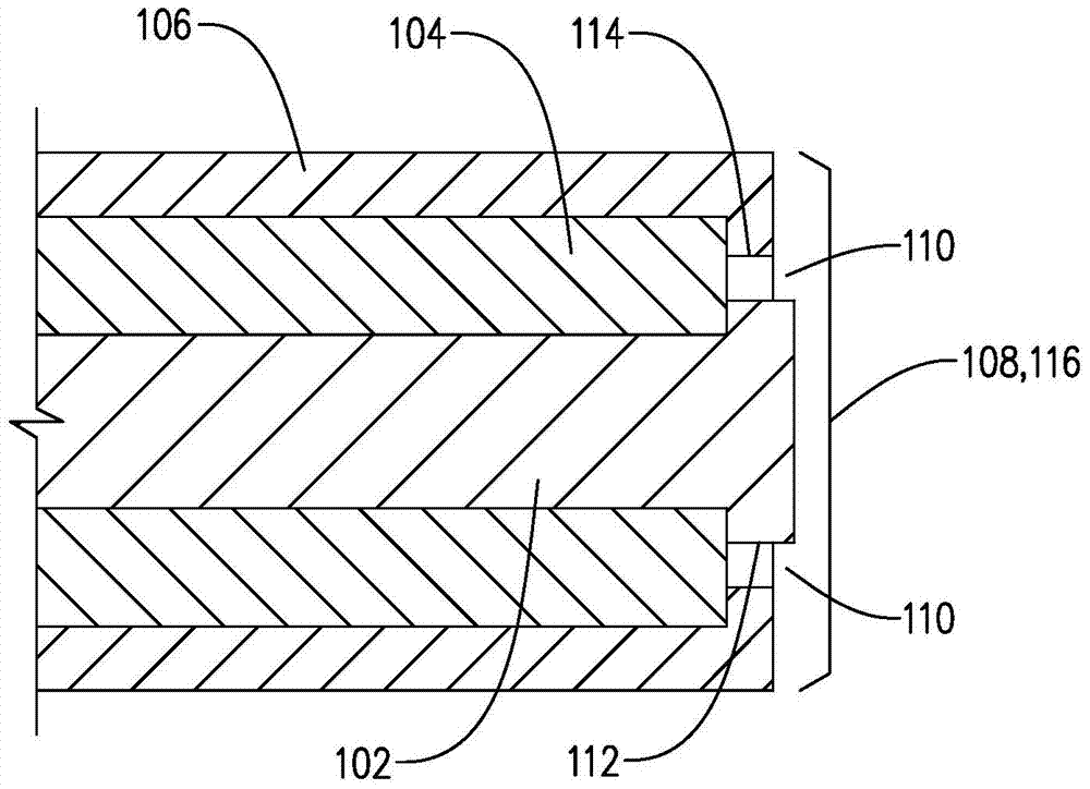
[0060] During the first test, a low energy HEI system (-0.33J) capable of fitting an igniter of approximately 1 / 4 inch diameter was used. Stated another way, the igniter OD, as defined by the outer diameter (OD) of the housing electrode, is 1 / 4 inch in diameter. During this project, three side-firing igniter geometries or radially directed spark igniters were tested. (Refer to Table 1 for specific parameters regarding the geometry.) Table 1 reflects the results of experiments performed with the side-firing design. The results show that by reducing the groove depth and having beveled electrodes and insulators, the electric field concentration betwee...


PUM


Abstract

The disclosure pertains to ignition systems and more particularly to spark igniters for burners and burner pilots. The spark igniter provided, is configured such that an electric field concentration between two electrodes increases while keeping output voltage unchanged.

Description

[0001] Cross References to Related Applications [0002] This application claims the benefit of US Provisional Application No. 61 / 920,812, filed December 26, 2013, which is incorporated herein by reference. technical field [0003] This application relates to ignition systems and more particularly to spark igniters for burners and burner pilots. Background technique [0004] A gas burner pilot is a device used to establish a stable pilot flame by burning a gaseous fuel-air mixture at a low flow rate (relative to the main burner). The pilot flame is used to ignite larger main burners, or to ignite difficult-to-ignite fuels. Gas pilot burner designs typically include an ignition system. One common type of ignition system used in gas burner pilot burners, as well as other burner systems such as flare systems, is the high energy ignition (HEI) system. [0005] In industry, HEI systems are used due to their ability to reliably ignite light or heavy fuels under cold, wet, dirty...

Claims


Application Information

Patent Timeline
Patent Type & Authority Patents(China)
IPC IPC(8): F23Q3/00
CPCF23Q3/004H01T1/22H01T13/20H01T13/52F02P13/00H01T13/22F23Q3/00
Inventor A·H·斯特朗E·M·凯利
Owner JOHN ZINK CO LLC
Features
  • R&D
  • Intellectual Property
  • Life Sciences
  • Materials
  • Tech Scout
  • Unparalleled Data Quality
  • Higher Quality Content
  • 60% Fewer Hallucinations
Learn More