Radio frequency tag positioning method and system

A technology of radio frequency tags and positioning methods, applied in the field of radio frequency identification, can solve the problems of expensive, non-promotable and universal, and achieve the effect of improving accuracy

Active Publication Date: 2015-07-01
WUXI TSINGHUA NAT LAB FOR INFORMATIONSCI & TECH INTERNET OF THINGS TECH CENT
View PDF6 Cites 10 Cited by
  • Summary
  • Abstract
  • Description
  • Claims
  • Application Information

AI Technical Summary

Problems solved by technology

However, this type of positioning method usually relies on expensive professional equipment, so it is not popular and universal

Method used


Image

  • Radio frequency tag positioning method and system
  • Radio frequency tag positioning method and system
  • Radio frequency tag positioning method and system

Examples


Embodiment 1

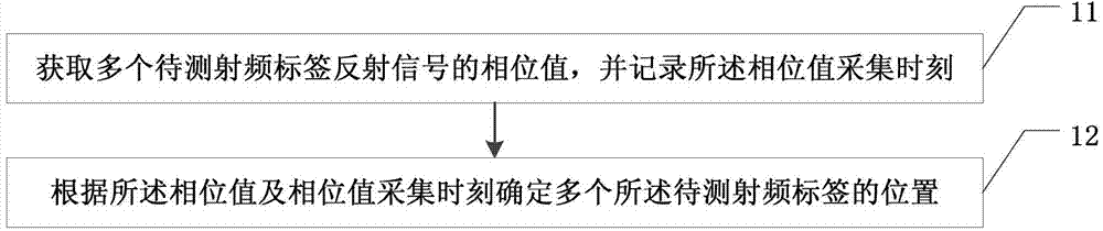
[0046] figure 1 For a flow chart of a radio frequency tag positioning method provided in Embodiment 1 of the present invention, see figure 1 , the method includes:

[0047] Step 11. Obtain phase values ​​of reflected signals of multiple radio frequency tags to be tested, and record the acquisition time of the phase values.

[0048] Among them, a plurality of radio frequency tags to be tested are attached to the object to mark the position of the object. The radio frequency tags to be tested can receive the detection signal transmitted by the directional antenna, and after receiving the detection signal, transmit a reflected signal to the radio frequency receiver , the reflected signal carries phase information, and the phase information reflects the distance between the radio frequency tag to be tested and the directional antenna. After the radio frequency receiver extracts the phase value from the received reflected signal, it records the acquisition time of the phase value...

Embodiment 2

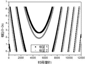
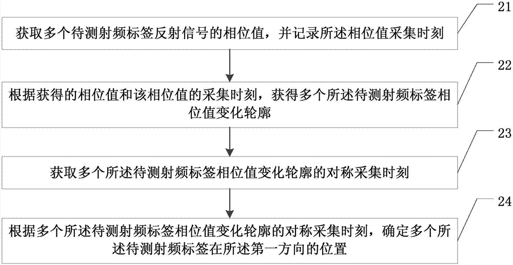
[0054] figure 2 It is a flow chart of a radio frequency tag positioning method provided in Embodiment 2 of the present invention. In the embodiment of the present invention, by receiving the reflected signal of the radio frequency tag, using the time-space correlation of the phase of the reflected signal to infer the positional relationship of the tag in two-dimensional space, for example, it can be applied to the sequence of books on the bookshelf and the sequence of luggage on the conveyor belt exact sorting etc.

[0055] see figure 2 , the method includes:

[0056] Step 21. Obtain the phase values ​​of the reflected signals of multiple radio frequency tags to be tested, and record the acquisition time of the phase values.

[0057] This step is similar to the implementation process of step 11 in the first embodiment, and will not be repeated here.

[0058] Step 22: Obtain a plurality of phase value change profiles of the radio frequency tags to be tested according to t...

Embodiment 3

[0067] On the basis of the above embodiments, the embodiment of the present invention also provides a method for obtaining a plurality of phase value change profiles of the radio frequency tags to be tested, Figure 6 To obtain a flow chart of multiple phase value change profiles of the RF tag to be tested, see Figure 6 ,include:

[0068] Step 31, obtaining phase value vectors of a plurality of radio frequency tags to be tested;

[0069] For example, for a radio frequency tag P to be tested, at the acquisition time ti, the phase value of the radio frequency tag P to be tested obtained is pi, and a set of phase values ​​within a period of time T is collected to form a phase value vector P of the radio frequency tag P1 to be tested ( p1, p2, ... pi, ... pn), wherein, the length of the phase value vector P(p1, p2, ... pi, ..., pn) of the radio frequency tag to be tested is n, and n is the number of phase value collection points of the radio frequency tag to be tested. Similarl...


PUM


Abstract

The invention discloses a radio frequency tag positioning method; the method comprises the following steps: acquiring phase value of a plurality of radio frequency tag reflected signals to be detected, and recording the phase value acquisition time; confirming the positions of a plurality of radio frequency tags according to the phase value and the phase value acquisition time. The system comprises a plurality of radio frequency tags, the radio frequency tags are arranged in the first direction and / or in the second direction; a directional antenna used for emitting detection signal by a plurality of radio frequency tags and capable of moving along the first direction or the second direction; a radio frequency receiver used for acquiring the phase value of a plurality of radio frequency tag reflected signals to be detected, and recording the phase value acquisition time; the method does not rely on any professional equipment, additional landmark tags are not needed, and position positioning accuracy of the object marked with radio frequency tag can be improved.

Description

technical field [0001] The invention relates to the field of radio frequency identification, in particular to a radio frequency tag positioning method and system. Background technique [0002] How to obtain the location information of an object has always been one of the important issues concerned by the scientific research community. The position of an object can usually be divided into two types: absolute position and relative position. The absolute position of an object refers to the coordinates of the object in the world coordinate system. The relative position of the object refers to the relative position of the target object in a group of objects. For a long time, researchers have tried many methods to capture the absolute position of objects, and have achieved good positioning results. The positioning accuracy has gradually improved from the meter level to the decimeter level. However, upper-level applications based on object positions tend to pay more attention t...

Claims


Application Information

Patent Timeline
Patent Type & Authority Applications(China)
IPC IPC(8): G01S5/02
CPCG01S5/02
Inventor 上官龙飞杨铮朱彤刘云浩
Owner WUXI TSINGHUA NAT LAB FOR INFORMATIONSCI & TECH INTERNET OF THINGS TECH CENT
Why Eureka
Try Eureka