Cooling device and plasma processing equipment

A cooling device and equipment technology, applied in semiconductor/solid-state device manufacturing, discharge tubes, electrical components, etc., can solve the problems of cooling water leakage, poor sealing effect, scratches of sealing ring 4, etc., and achieve good sealing effect

Active Publication Date: 2017-02-15
BEIJING NAURA MICROELECTRONICS EQUIP CO LTD
View PDF4 Cites 0 Cited by
  • Summary
  • Abstract
  • Description
  • Claims
  • Application Information

AI Technical Summary

Problems solved by technology

[0007] First of all, in the above process, since the distance between the reaction chamber 1 and the transfer chamber 6 and the tail gas treatment system 7 is fixed, there is a tight seal between the reaction chamber 1 and the transfer chamber 6 and the tail gas treatment system 7. When the sealing ring 4 is subjected to the pressure of the tail gas treatment system 7 toward the reaction chamber 1 and the pressure of the reaction chamber 1 to the transfer chamber 6, the pressure is constant. In this case, the driving device 5 applies a When the force is greater, the pressure on the sealing ring 4 will not increase accordingly, which makes the contact between the sealing ring 4 and the transmission chamber 6 and the exhaust gas treatment system 7 not tight under certain circumstances, and its sealing effect poor, resulting in easy leakage of cooling water from the joint between the sealing ring 4 and the transmission chamber 6 and the exhaust gas treatment system 7
[0008] Secondly, in the plasma processing equipment, the reaction chamber 1 needs to be maintained frequently, and the water tank 2 needs to be disassembled during the maintenance process. The small distance or direct contact between them will cause friction between the sealing ring 4 and the transmission chamber 6 and the exhaust gas treatment system 7, and even cause the sealing ring 4 to be scratched, which makes the sealing ring 4 often need to be replaced in actual use. replacement, thereby increasing the maintenance cost of the reaction chamber 1

Method used


Image

  • Cooling device and plasma processing equipment
  • Cooling device and plasma processing equipment
  • Cooling device and plasma processing equipment

Examples


Embodiment Construction

[0031] In order for those skilled in the art to better understand the technical solutions of the present invention, the cooling device and the plasma processing equipment provided by the present invention will be described in detail below with reference to the accompanying drawings.

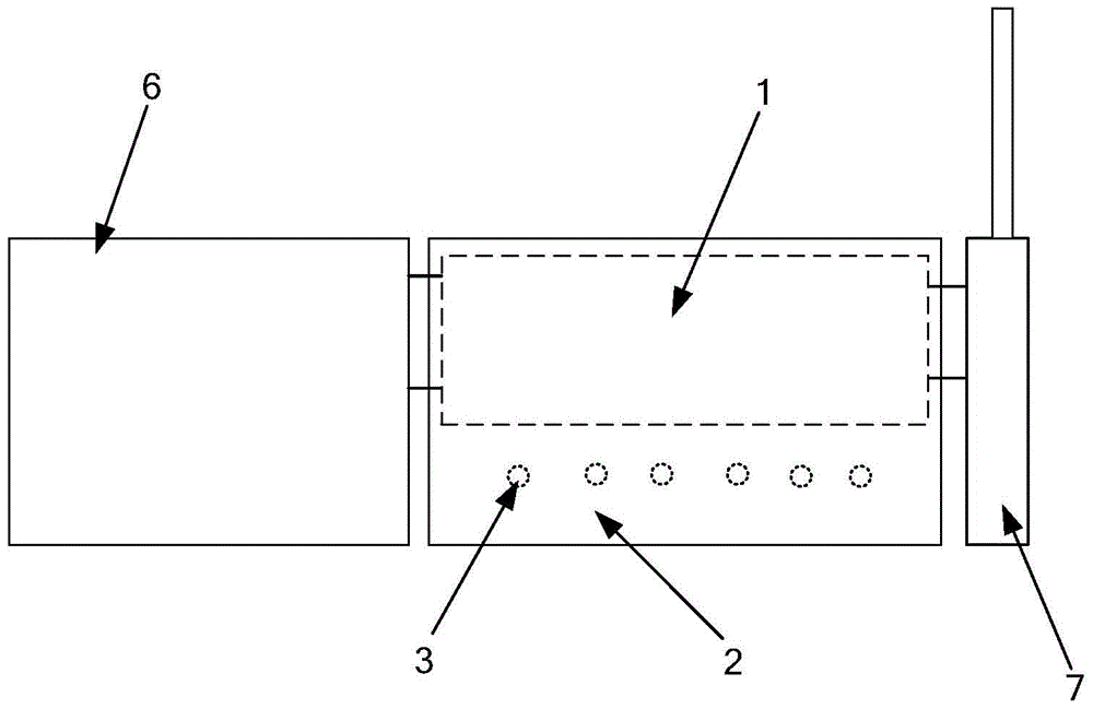
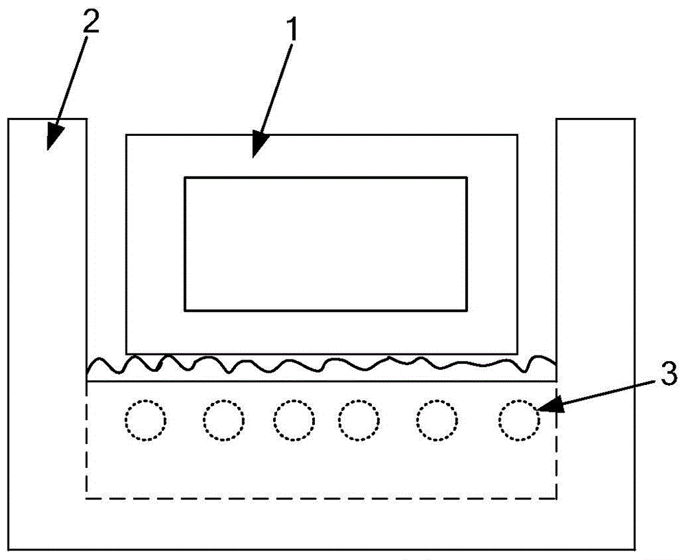
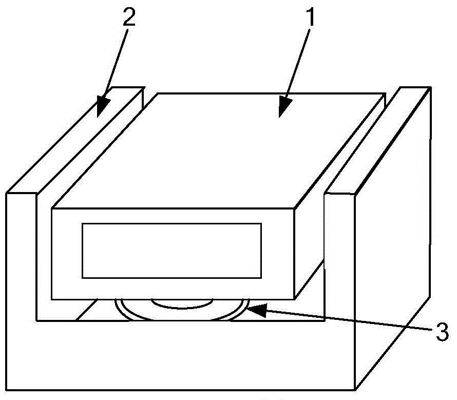
[0032] Please see Figure 5 and Image 6 , Figure 5 A schematic structural diagram of a cooling device provided for an embodiment of the present invention. Image 6 for Figure 5 Perspective view of the water tank in the chiller shown. Cooling device is used for cooling reaction chamber 20, and it comprises shower device 11, water tank 12, groove 13, sealing ring 14, gas source 15 and vacuumizing device 16; Wherein, reaction chamber 20 and transfer chamber 21, tail gas A first opening 200 is provided on the side corresponding to the corresponding equipment such as the treatment system 22 to communicate with the corresponding equipment such as the transfer chamber 21 and the tail gas treatment ...


PUM


Abstract

The invention relates to a cooling device and a piece of plasma processing equipment. The cooling device comprises a spraying device and a water tank. A side, directly facing a piece of corresponding equipment, of a reaction chamber is provided with a first opening used for communicating the reaction chamber with the corresponding equipment. The side wall of a side, the same as the first opening, of the water tank is provided with a second opening. The side, where the second opening is disposed, of the water tank is provided with a groove which surrounds the second opening along the two sides and the lower part of the second opening. A sealing ring matched with the groove is arranged in the groove, and a sealing space is formed between the sealing ring and the groove. The cooling device further comprises a gas source and a vacuum pumping device, both of which are communicated with the sealing space. The gas source is used for inputting gas into the sealing space when the cooling device is working so as to make the sealing ring partially extend out of the groove under the pressure of gas and make the sealing ring in close contact with the corresponding equipment. The vacuum pumping device is used for vacuum-pumping the sealing space when the cooling device is disassembled so as to enable the part of the sealing ring extending out of the groove retract into the groove.

Description

technical field [0001] The invention relates to the technical field of microelectronic processing, in particular to a cooling device and plasma processing equipment. Background technique [0002] figure 1 A schematic diagram of the plasma processing equipment. like figure 1 As shown, the plasma processing equipment includes a reaction chamber 1, a transmission chamber 6, an exhaust gas treatment system 7 and a heating coil 3; wherein, the two sides of the reaction chamber 1 have lateral openings, which are respectively used for connecting with the transmission chamber 6, the The tail gas treatment system 7 is sealed and connected so that the manipulator located inside the transfer chamber 6 transmits the processed workpiece to the inside of the reaction chamber 1, and the gas in the reaction chamber 1 is discharged from the tail gas treatment system 7; the heating coil 3 is used for The tray in the reaction chamber 1 is heated to make it have a higher temperature and make...

Claims


Application Information

Patent Timeline
Patent Type & Authority Patents(China)
IPC IPC(8): H01J37/32H01L21/67
Inventor 蒲春
Owner BEIJING NAURA MICROELECTRONICS EQUIP CO LTD
Why Eureka
Try Eureka