Cassette positioning device and semiconductor processing device

A technology for positioning devices and cassettes, applied in semiconductor/solid-state device manufacturing, electrical components, circuits, etc., can solve problems such as non-unique positions, inconvenient maintenance, reduced transmission and process efficiency, and achieve the effect of improving efficiency

Active Publication Date: 2015-07-01
BEIJING NAURA MICROELECTRONICS EQUIP CO LTD
View PDF5 Cites 11 Cited by
  • Summary
  • Abstract
  • Description
  • Claims
  • Application Information

AI Technical Summary

Problems solved by technology

Yet because the operator manually places the cassette 1 on the positioning plate 7, this operation is often affected by factors such as speed, strength and angle, so that the center of some wafers 6 in the cassette 1 (such as Figure 4B d / 2 radius in , where d is the diameter of the wafer 6) will deviate from the center O2 of the pick-up position, causing these wafers 6 to deviate from the only designated position on the manipulator 4 when they are taken out by the manipulator 4, thus causing different wafers 6 to be placed on the manipulator. The position on 4 is not unique, which reduces the efficiency of subsequent transmission and process
[0006] In practical applications, although an additional wafer alignment device can be set up to be used in conjunction with the manipulator to solve the problem that the positions of different wafers on the manipulator are not unique, the cost of the wafer alignment device is relatively high, and it is inconvenient to maintain, thus increasing the cost of semiconductor devices. Manufacturing and operating costs of processing equipment

Method used


Image

  • Cassette positioning device and semiconductor processing device
  • Cassette positioning device and semiconductor processing device
  • Cassette positioning device and semiconductor processing device

Examples


no. 1 example

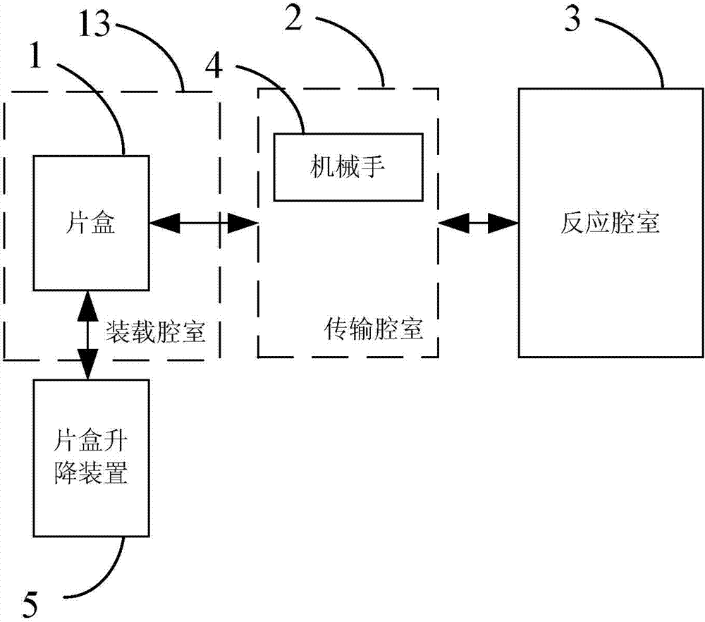
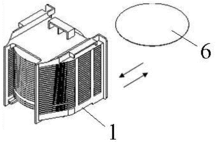
[0041] Please also refer to Figures 5A-5E , the film cassette positioning device provided by the first embodiment of the present invention is located in the loading chamber 20 for accommodating the film cassette 33, and is driven by the lifting device 31 to move linearly in the vertical direction to cooperate with the manipulator (Fig. (not shown in ) completes taking or putting the film from the film box 33.

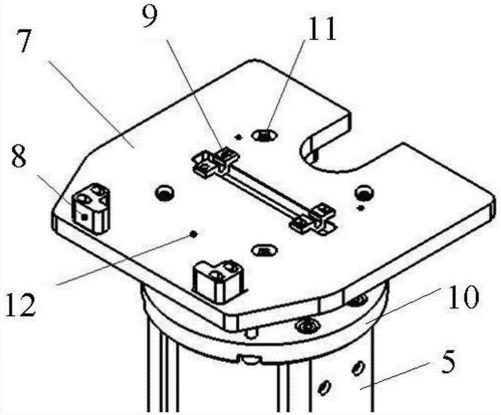
[0042] The cassette positioning device includes a positioning bottom plate 21 , a rotating positioning plate 22 and a support column 23 . Wherein, the positioning base plate 21 is arranged horizontally, and is connected with the elevating device 31. In the present embodiment, the elevating device 31 has a connecting plate 32 arranged horizontally, and the positioning base plate 21 is screwed on the connecting plate 32 by screws 24 to realize the lifting and lowering. Device 31 connections. Preferably, set screws 25 are also provided on the positioning bottom plate 21...

no. 2 example

[0051] Figure 7A It is a schematic diagram of the cassette positioning device provided by the second embodiment of the present invention. Figure 7B for Figure 7A Enlarged view of region II in middle. Please also refer to Figure 7A and Figure 7B , the cassette positioning device provided in this embodiment also includes a positioning bottom plate 21 , a rotating positioning plate 22 and a support column 23 . The structures and functions of the positioning bottom plate 21 , the rotating positioning plate 22 and the support column 23 are the same as those of the above-mentioned first embodiment, and since they have been described in detail in the above-mentioned first embodiment, they will not be repeated here. Only the differences between this embodiment and the above-mentioned first embodiment will be described in detail below.

[0052] Specifically, the cassette positioning device further includes a support column lifting mechanism 34 for driving the support column 2...


PUM


Abstract

Provided are a cassette positioning device and a semiconductor processing apparatus. The cassette positioning device comprises a positioning base plate (21), a rotary positioning plate (22) and a supporting post (23). The positioning base plate (21) is arranged horizontally and connected to a lifting device (31). The rotary positioning plate (22) is arranged on the positioning base plate (21) and has one end rotatably connected to one end of the positioning base plate (21). A positioning component is arranged on the rotary positioning plate (22). The supporting post (23) is arranged below the rotary positioning plate (22), and can move relative to the positioning base plate (21) in the vertical direction, so that when the supporting post (23) rises to a preset highest position relative to the positioning base plate (21), the rotary positioning plate (22) is pushed against by the supporting post (23) and rotated to a position inclined with respect to the positioning base plate (21); when the supporting post (23) is located at a preset lowest position, the rotary positioning plate (22) is stacked on and parallel to the positioning base plate (21). By means of the cassette positioning device and the semiconductor processing apparatus, all wafers in a cassette (33) can have identical positions in the horizontal direction, so that wafers fetched by a mechanical arm are all located at a unique designated position on the mechanical arm.

Description

technical field [0001] The invention relates to the technical field of microelectronic processing, in particular to a chip box positioning device and semiconductor processing equipment. Background technique [0002] Removing wafers from cassettes is the first step in the automated transfer process of many semiconductor processing equipment, so the efficiency and reliability of wafer removal has become one of the important prerequisites for highly automated wafer production. [0003] figure 1 Schematic block diagram of semiconductor processing equipment. Such as figure 1 As shown, the semiconductor processing equipment includes a loading chamber 13 , a transfer chamber 2 and a reaction chamber 3 . Wherein, the loading chamber 13 is used to carry the cassette 1; the cassette 1 is used to carry a plurality of wafers, and its specific structure is as follows: figure 2 As shown, the left, right and rear ends of cassette 1 ( figure 2 The left side, the right side and the fr...

Claims


Application Information

Patent Timeline
Patent Type & Authority Applications(China)
IPC IPC(8): H01L21/68
CPCH01L21/68H01L21/67778H01L21/67775H01L21/67796
Inventor 李萌张风港丁培军赵梦欣刘菲菲张文
Owner BEIJING NAURA MICROELECTRONICS EQUIP CO LTD
Why Eureka
Try Eureka