Frequency selectivity antenna

A frequency selective, antenna technology, applied in antenna coupling, antenna grounding switch structure connection, etc., can solve the problem of poor anti-band interference ability, and achieve the effect of high reliability, high efficiency and low cross-polarization performance of the antenna

Active Publication Date: 2015-07-01
CHINA ELECTRONIC TECH GRP CORP NO 38 RES INST
View PDF3 Cites 6 Cited by
  • Summary
  • Abstract
  • Description
  • Claims
  • Application Information

AI Technical Summary

Problems solved by technology

[0008] In order to solve the problem of poor anti-out-of-band interference ability of existing antennas, reduce the difficulty of system anti-interference design, and improve cross-polarization suppression performance, the present invention provides a method that can realize the matching transmission of the working frequency band of the system and suppress the transmission of electromagnetic waves in other frequency bands. A frequency-selective antenna that eliminates out-of-band interference is applied to phased array antennas such as two-dimensional large-angle scanning situations, and additional current-limiting slits greatly improve cross-polarization suppression performance

Method used


Image

  • Frequency selectivity antenna
  • Frequency selectivity antenna
  • Frequency selectivity antenna

Examples


Embodiment 1

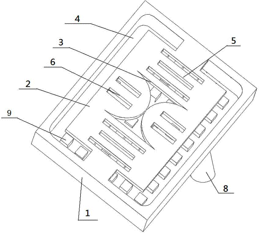
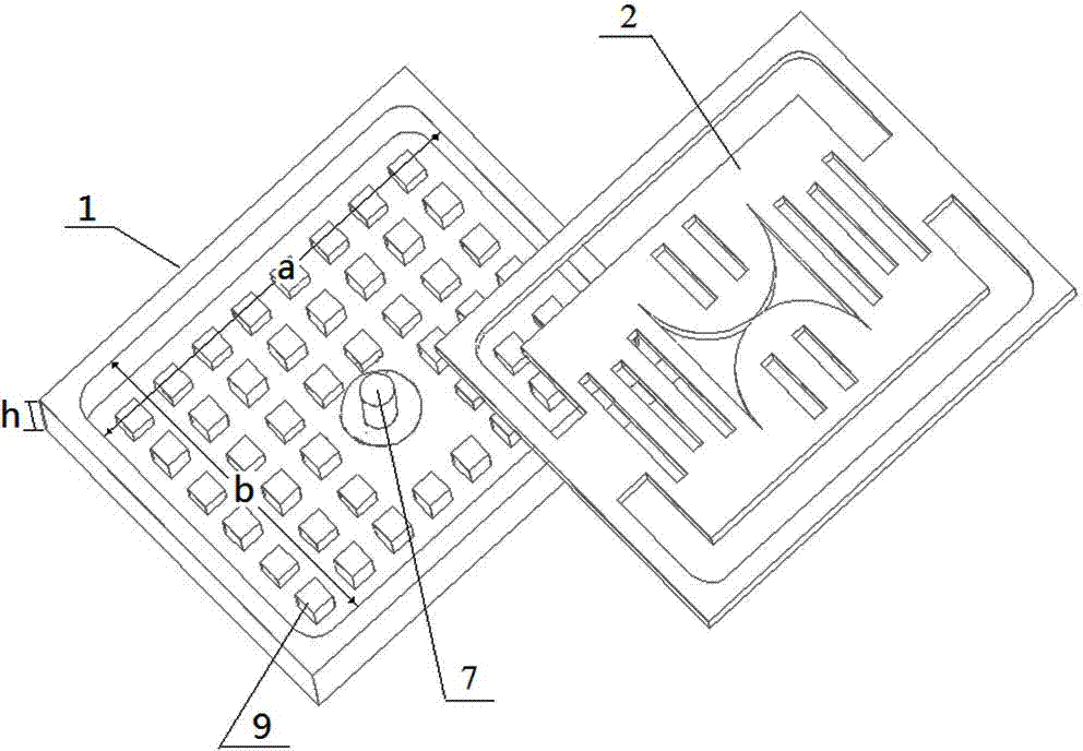
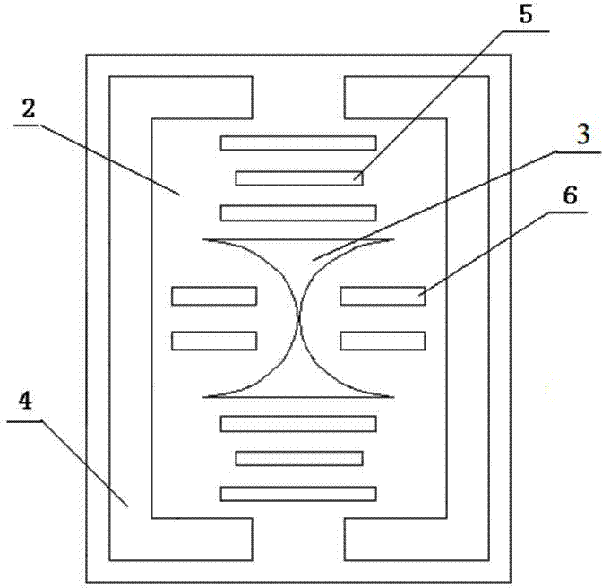
[0041] see figure 1 and figure 2 , a frequency selective antenna includes a flat box-shaped hollow metal cavity 1, the top 2 of the metal cavity 1 is provided with a []-shaped radiation slot 4, and the middle part is provided with an X-shaped radiation slot 3, and the X-shaped radiation slot 3 The top 2 of the metal cavity 1 corresponding to the top and bottom of the X-shaped radiation slit 3 is provided with three-shaped slits 5 with limited flow, and the top 2 of the metal cavity 1 corresponding to the left and right sides of the X-shaped radiation slit 3 is respectively provided with two slits with limited flow. Zigzag slits 6; the inner bottom of the metal cavity 1 is uniformly provided with upright metal columns 9, and the metal columns 9 are hexagonal or cylindrical, Figure 12 The metal pillars in are hexagonal, Figure 13 The metal pillar in the center is circular, and its function is to limit the work of high-frequency out-of-band electromagnetic waves in the cavit...

Embodiment 2

[0054] see Figure 14 , using a frequency-selective antenna of Embodiment 1 as the antenna unit, an 8×8 planar antenna array is obtained by extension, and the side walls of the metal cavities 1 of adjacent antenna units are all common walls; the 8×8 planar The antenna array can be processed as a module of the planar phased array antenna, and the large array can be extended by this module. It can be seen that when multiple units are integrated, the antenna array is structurally similar to a honeycomb structure.


PUM


Abstract

The invention relates to a frequency selectivity antenna. The frequency selectivity antenna comprises a flat box-shaped hollow metal cavity, wherein a radiating slot is formed at the top of the metal cavity and a plurality of metal columns and a coaxial connector are arranged at the bottom of the metal cavity; the radiating slot comprises X-shaped radiating slot formed at the middle position and []-shaped radiating slots formed at two sides; the tops of the metal cavities above and below the []-shaped radiating slots are respectively provided with the slot of the Chinese character san, the tops of the metal cavities at the left side and the right side of the X-shaped radiating slot are respectively provided with the slot of the Chinese character er; the frequency selectivity antenna works at the X wave band and has stable band interior radiation characteristic and band-pass filter characteristic and has extremely low cross polarization performance. The frequency selectivity antenna can restrain radio frequency signal outside the work frequency band, additional device is not needed and additional loss is not generated; compared with the microstrip antenna, the loss is relatively low and the efficiency is high; compared with the opening waveguide antenna, the cross section of the cavity structure is lower and is 0.1 (center center frequency wave length), the opening waveguide is greater than 0.25.

Description

technical field [0001] The invention belongs to the technical field of antennas, in particular to metal cavity slot antennas. The invention can be used both for receiving and for transmitting radio waves. In military terms, it can be used as a terminal antenna for anti-jamming phased array radar systems. In civilian use, it can be used as an antenna for communication, weather radar, air traffic control radar and other systems. Background technique [0002] With the rapid development of applications and requirements, the use of electromagnetic spectrum has been greatly expanded and fully applied, and it is becoming more and more crowded. On the one hand, there are more and more electronic devices working at various frequencies; on the other hand, some platforms such as ships, aircraft and satellites are limited in space. In the case of such a high-density spectrum, the electromagnetic environment of each electronic device is very harsh. Therefore, electromagnetic compatibi...

Claims


Application Information

Patent Timeline
Patent Type & Authority Applications(China)
IPC IPC(8): H01Q1/52H01Q1/50
Inventor 汪伟孙立春张洪涛金谋平鲁加国
Owner CHINA ELECTRONIC TECH GRP CORP NO 38 RES INST
Why Eureka
Try Eureka