
Method for fabricating loudspeaker

A manufacturing method and speaker technology, which are applied to sensors, electrical components, etc., can solve the problems of high overall height of the speaker, asynchronous vibration, and difficulty in achieving thin, small and miniaturization, so as to solve the problem of uneven frequency response curve, reduce deformation and make Simple and convenient method

Active Publication Date: 2015-07-01
SHENZHEN GRANDSUN ELECTRONICS
View PDF5 Cites 1 Cited by
  • Summary
  • Abstract
  • Description
  • Claims
  • Application Information

AI Technical Summary

Problems solved by technology

[0005] The purpose of the present invention is to overcome the defects of the prior art and provide a manufacturing method of the loudspeaker to solve the problem that the overall height of the loudspeaker in the prior art is large and it is difficult to realize thinness and miniaturization. When the vibrating membrane encounters medium and high frequency vibration, it is easy to have the problem of asynchronous vibration at each position

Method used


Image

  • Method for fabricating loudspeaker
  • Method for fabricating loudspeaker
  • Method for fabricating loudspeaker

Examples


Embodiment 1

[0041] see Figure 4 to Figure 11 , the loudspeaker according to the embodiment of the present invention will be described below.

[0042] The manufacturing method of the loudspeaker of the present embodiment comprises the following steps:

[0043] Step S101, preparing a support frame 10 for component installation;

[0044] Step S102, preparing a radial vibrating membrane 21, the center of the vibrating membrane 21 is provided with a spherical convex portion 211 protruding outward;

[0045] Step S103, preparing a disc-shaped voice coil 22, the transverse width of the voice coil 22 is greater than the longitudinal height of the voice coil 22, generally, the transverse width of the voice coil 22 is more than 10 times the longitudinal height of the voice coil 22;

[0046] Step S104, sticking the voice coil 22 on the bottom end surface of the vibrating membrane 21, and making it close to the lowest position in the longitudinal direction of the inner wall of the dome convex porti...

Embodiment 2

[0069] see Figure 12 , and combined with Figure 4 to Figure 11 , the implementation of Embodiment 2 is similar to that of Embodiment 1. For details, please refer to the implementation of Embodiment 1, which will not be described in detail here, and the difference between the two is:

[0070] In the second embodiment, the voice coil 22 is arranged on the inner wall surface of the spherical convex portion 211 . However, this embodiment can also better ensure that the vibrating assembly 20 composed of the voice coil 22 and the vibrating membrane 21 can vibrate better to generate sound.


PUM

PropertyMeasurementUnit
Diameteraaaaaaaaaa
Outer circle diameteraaaaaaaaaa
Inner circle diameteraaaaaaaaaa

Abstract

The invention disclose a method for fabricating a loudspeaker. The method comprises the following steps of preparing a support frame; preparing a vibrating membrane, wherein a globe-roof convex part is arranged at the center of the vibrating membrane; preparing a round-dish voice coil; pasting the voice coil on the bottom end of the vibrating membrane, thereby assembling the voice coil and the vibrating membrane into a vibrating assembly; arranging the vibrating assembly on the support frame; preparing a radial magnet; arranging the radial magnet above the support frame and below the vibrating assembly; preparing a PCB (printed circuit board); arranging the PCB on the support frame and allowing the PCB to electrically connect the vibrating assembly. The fabricating method is characterized in that the voice coil is in a round-dish structure, and the total height from the voice coil to the loudspeaker reaches below 4.2mm when the voice coil is pasted on the bottom end of the vibrating membrane, so that the loudspeaker is thinned and miniaturized; meanwhile one round-dish voice coil is superimposed on the vibrating membrane, so that the deformation of the vibrating membrane can be greatly reduced in a vibrating process, and the uneven frequency response curve caused by segmentation and vibration can be solved.

Description

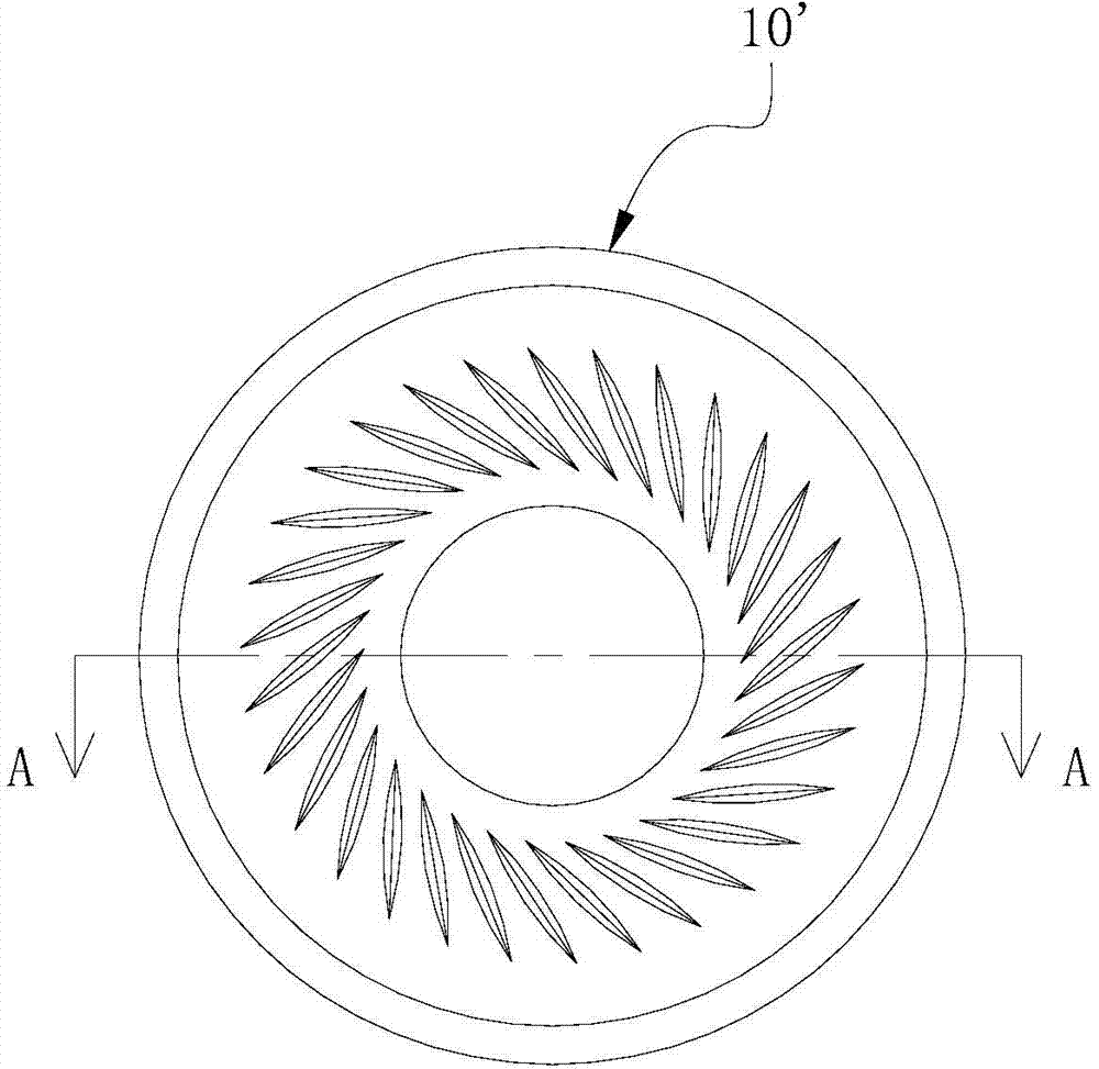
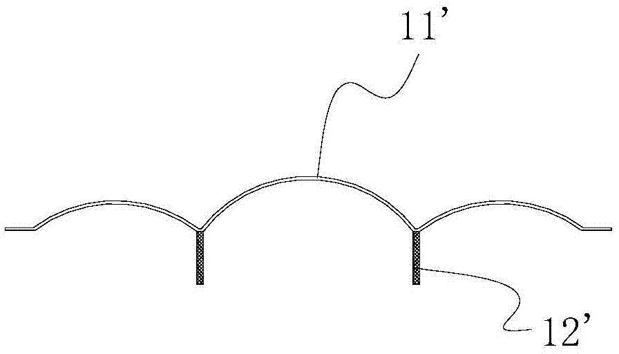
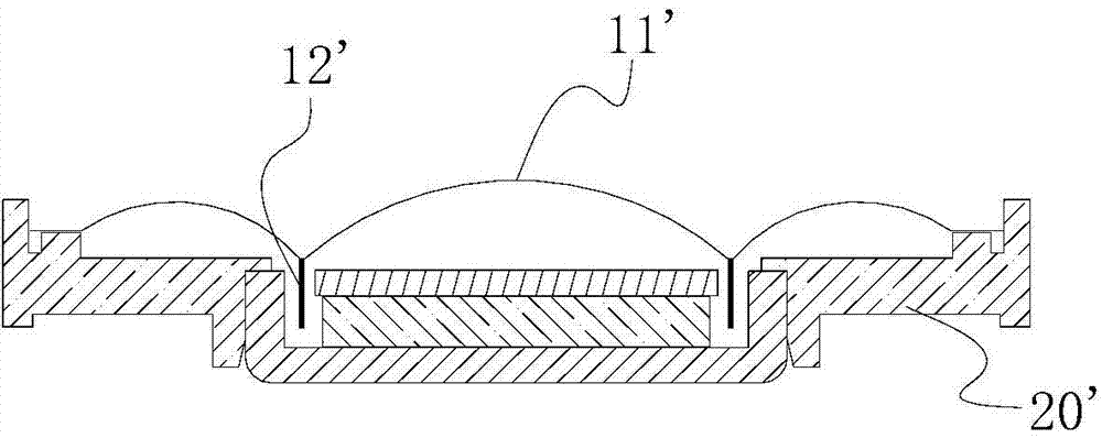
technical field [0001] The invention relates to the technical field of electroacoustic transducer elements, in particular to a manufacturing method of a loudspeaker. Background technique [0002] In the field of modern acoustic and electric technology, the loudspeaker, also known as the horn, is an important transducer device, which is commonly found in various communication equipment, audio-visual equipment and other electronic devices. A uniform magnetic field is formed inside the speaker, and the voice coil made of conductive material is suspended in the uniform magnetic field of the speaker. Due to the action of the Loren magnetic force, when the signal carrying the sound characteristics in the voice coil changes, the voice coil will vibrate, which will drive the diaphragm to emit sound, and realize the conversion of electrical signals into sound. [0003] At present, the dynamic speaker is mainly composed of a support frame 20', a vibration assembly 10' disposed on the...

Claims


Application Information

Patent Timeline
IPC IPC(8): H04R31/00
Inventor 窦力才彭信龙吴海全师瑞文
Owner SHENZHEN GRANDSUN ELECTRONICS
Learn More