Data transmission control method and data transmission control device

A technology for data transmission control and data uploading, which is applied in network traffic/resource management, electrical components, wireless communication, etc. It can solve problems such as base station congestion, high concurrent processing pressure on the server, and inability to solve equipment, so as to avoid power consumption Increase, solve the problem of timing transmission failure, and avoid the effect of repeated confirmation

Active Publication Date: 2015-07-01
CHINA MOBILE COMM GRP CO LTD
View PDF4 Cites 23 Cited by
  • Summary
  • Abstract
  • Description
  • Claims
  • Application Information

AI Technical Summary

Problems solved by technology

[0008] The present invention provides a data transmission control method and device, which can effectively solve the large concurrent processing

Method used


Image

  • Data transmission control method and data transmission control device
  • Data transmission control method and data transmission control device
  • Data transmission control method and data transmission control device

Examples


Embodiment 1

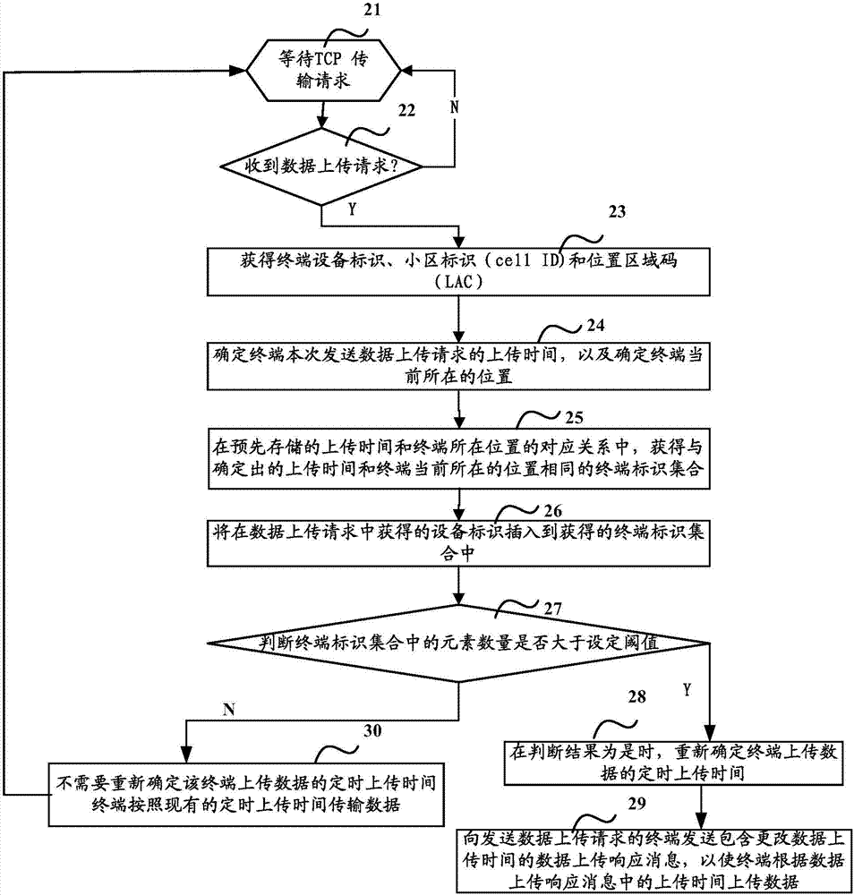
[0058] The embodiment of the present invention proposes a data transmission control method, which can be applied on the server side. The server counts the cellID and LAC when each terminal uploads data multiple times, determines the base station information of the terminal at the time of uploading, and maintains all terminals The list of upload time and base station information is detected every time a TCP connection is established. When it is found that there are too many terminals uploading data at the same time at the same base station, a configuration signaling is issued to adjust the upload time of the base station equipment. like figure 2 As shown, the specific process is as follows:

[0059] Step 21: Establish a data transmission link between the server and the terminal based on the transmission control protocol, and wait for receiving a data transmission request.

[0060] Step 22, for any terminal, judge whether the data upload request sent by the terminal is receive...

Embodiment 2

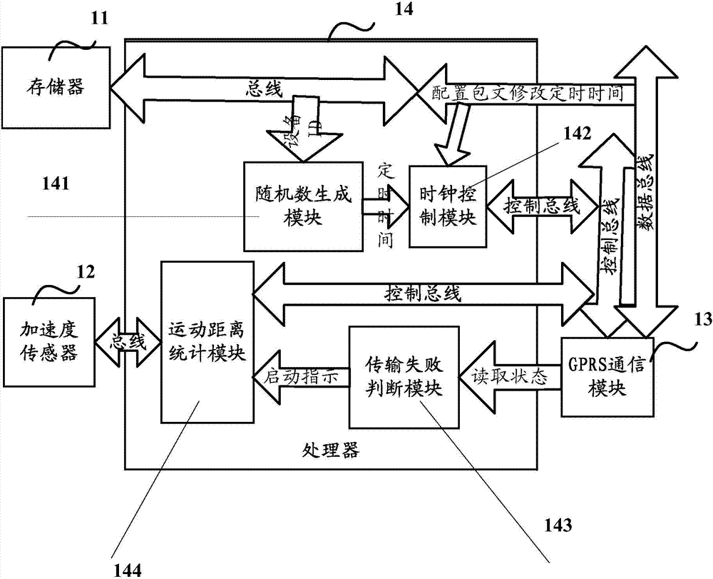
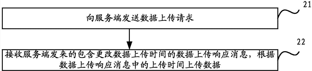
[0102] Based on attached figure 1 For the proposed motion detection device, Embodiment 2 of the present invention proposes a data transmission control method. In the technical solution proposed in Embodiment 2 of the present invention, the motion detection device can automatically upload data at a set transmission time T such as early in the morning. In the case of data transmission failure, for example, data transmission failure occurs for 3 consecutive days, the motion detection device stops uploading data at the set transmission time, and starts timing after detecting that the movement distance of the motion detection device exceeds the threshold L (such as 500m) Upload, at this time, it can be considered that the user has left the area with poor signal coverage at this time. If the upload is successful, record time T1 as the candidate time T for the new automatic transmission time. If the upload fails this time, continue to exercise Distance judgment, start the automatic u...


PUM


Abstract

The invention discloses a data transmission control method and a data transmission control device. The data transmission control method comprises the steps of determining an equipment identifier, which is included in a received data upload request sent by a terminal, of the terminal and determining the upload time in the data upload request sent by the terminal; determining a current location of the terminal according to a cell identifier and a location area code; acquiring a terminal identifier set in a corresponding relation between the pre-stored upload time and the location of the terminal; inserting the terminal identifier acquired in the data upload request into the acquired terminal identifier set; judging whether the number of elements in the terminal identifier set is greater than a set threshold value or not; re-determining the timing upload time when the terminal uploads data if the judgment result is that the number of the elements in the terminal identifier set is greater than the set threshold value; and sending a data upload response message to the terminal which sends the data upload request. According to the invention, a problem of base station congestion caused by simultaneous uploading of equipment at the same place because great concurrent processing pressure is generated for a server can be effectively solved.

Description

technical field [0001] The present invention relates to the technical field of wireless communication, in particular to a data transmission control method and device. Background technique [0002] With the development of high-tech such as mobile communication, somatosensory network and sensors, the technical field of mobile health has increasingly shown broad market prospects. In the mobile health application, the portable motion detection device can record the user's motion behavior in real time, and transmit the recorded data to the data center (server) of the remote health care service provider through the wireless network, which is completed by the data center Management analysis of personal sports data. The portable motion detection device can use the client or browser (web) page of the mobile terminal to present motion records and trends, and give feedback on sports, weight loss, health care and other guidance. [0003] With the rise and development of the Internet o...

Claims


Application Information

Patent Timeline
IPC IPC(8): H04W28/02
CPCH04W28/0247H04W28/0289
Inventor 王义许利群
Owner CHINA MOBILE COMM GRP CO LTD
Why Eureka
Try Eureka