Two-edge double margin drill

A technology of drill bits and margins, which is used in repair drills, twist drills, drilling tool accessories, etc., can solve problems such as unstable steering and difficulty in improving hole drilling accuracy.

Active Publication Date: 2015-07-01
SUMITOMO ELECTRIC HARDMETAL CORP
View PDF6 Cites 11 Cited by
  • Summary
  • Abstract
  • Description
  • Claims
  • Application Information

AI Technical Summary

Problems solved by technology

Therefore, for example, when drilling with such a drill at a high feed rate, the guidance at the initial stage of forming the drilled hole becomes unstable, making it difficult to improve the drilling accuracy of the hole

Method used


Image

  • Two-edge double margin drill
  • Two-edge double margin drill
  • Two-edge double margin drill

Examples


example 1

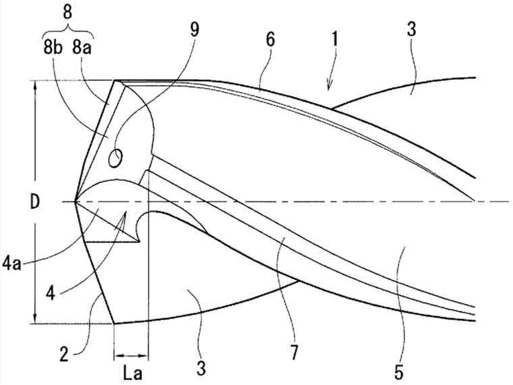
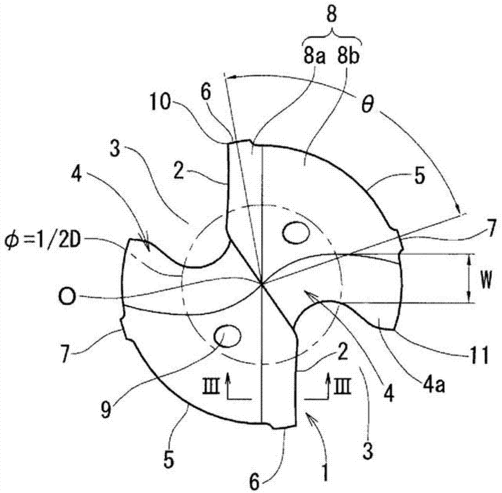
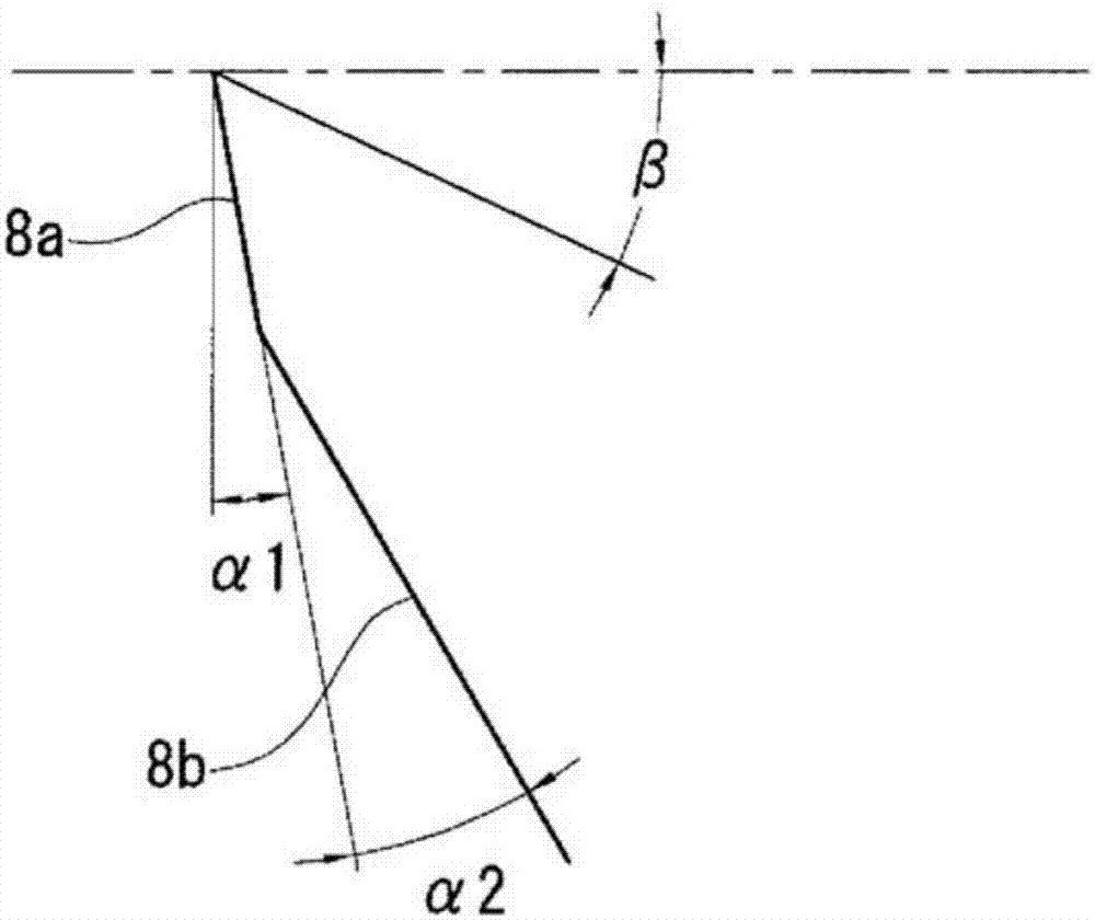
[0049] Trial out with Figure 4 and Figure 5 Bits of the shape shown. The size of the drill bit is: diameter D=13mm, center thickness=4.6mm, helix angle β=30° of each helical chip flute, clearance angle α1=9° of each second flank, and α1=9° of each third flank The clearance angle α2 = 15°, and at a distance equal to (1 / 2)D from the center of rotation, the width W of each ground chisel surface in the end view of the drill bit = 2.3mm.

[0050] The trial-manufactured drill provides the R-shaped chisel edge part shown in the figure, which prevents the chisel edge from being cut to the end of the secondary margin, and can be connected from the outer end of each cutting edge to the corresponding secondary margin. The axial distance La is shortened to 0.4mm. Furthermore, it is possible to set the circumferential interval θ between the primary land and the corresponding secondary land to 90°. Therefore, even if the drilling operation (workpiece: cast iron) is performed under the...

example 2

[0053] The drills I to III were used, and the difference in the positional accuracy of the hole caused by the difference between the clearance angles of the third flank was checked. For drill bits I to III, set according to table 1 Figure 6A The shown clearance angle α1 of the second flank and clearance angle α2 of the third flank, Figure 6B Shown are the axial distance La from the outer end of the cutting edge to the secondary land and the distance Lb from the position where the primary land acts to the secondary land (the section where the secondary land does not function).


PUM

PropertyMeasurementUnit
diameteraaaaaaaaaa
thicknessaaaaaaaaaa

Abstract

The present invention addresses the problem of making it possible to shorten as much as possible the distance in the axial direction from the primary margin to the secondary margin of a two-edge double margin drill and to keep the interval between the primary margin and the secondary margin within an ideal range. The interval (θ) between the primary margin (6) and the secondary margin (7) provided on the outer circumference of land sections (5) is set to be 80° - 100°. The flanks (8) are configured from a second flank (8a) and a third flank (8b) that are coplanar. Moreover, at the central part of the tip, thinning sections (4) having thinning surfaces (4a) that form convex arcs in the direction of drill rotation in front view of the drill are formed, and the outer edges of the thinning surfaces (4a) in the radial direction are disposed behind the leading end of the secondary margin (7) in the direction of drill rotation and are extended to the circumference of the land sections (5).

Description

technical field [0001] The present invention relates to a two-flute drill comprising primary and secondary lands at each of the two lands, and more particularly to a method for maximizing the guiding effect of the margins while allowing A two-edged, double-margin drill with a shortened axial distance from the primary land to the corresponding secondary land. Background technique [0002] The aforementioned two-edged double-margin drill is an ideal drill, in which, in order to maximize the guiding function provided by the margin, the major margin and the minor margin are arranged at equal intervals (90° intervals), and the major margin is corresponding to the minor margin. The distance of the margin (the amount of retreat from the main margin to the corresponding secondary margin) is short. [0003] However, in order to reduce the thrust force, the chisel edge is usually ground to reduce the chisel edge width at the end of the drill. When the chisel processing is the X-type...

Claims


Application Information

Patent Timeline
Patent Type & Authority Applications(China)
IPC IPC(8): B23B51/00
CPCB23B51/02B23B2251/443B23B2251/18Y10T408/9097B23B2251/14
Inventor 佐藤佳司栗塚和昌神代政章
Owner SUMITOMO ELECTRIC HARDMETAL CORP
Why Eureka
Try Eureka