Cab Reinforcement Structure

A cab and structure technology, applied in the field of cab reinforcement structure, can solve problems such as collapse, increased deformation, and inability to exert strength, and achieve the effect of ensuring living space and suppressing flattening deformation

Inactive Publication Date: 2017-04-19
HINO MOTORS LTD
View PDF1 Cites 0 Cited by
  • Summary
  • Abstract
  • Description
  • Claims
  • Application Information

AI Technical Summary

Problems solved by technology

[0006] However, the reinforcement structure of the driver's cab 1 so far only corresponds to the conventional test in which the upper surface of the driver's cab 1 is hit with the impact head 2' and a load is applied in the vertical direction. For example, image 3 In the same way as shown in the indoor view of the backboard 4 on the conventional cab 1, the reinforcement beam 5 is installed on the upper wall surface of the indoor side of the backboard 4 throughout the entire area in the vehicle width direction, and at the same time, the above-mentioned backboard 4 A pair of reinforcing columns 10, 11, which stand upright from the floor 9 directly above the rear cab brackets 7, 8 supporting the rear of the cab 1 from the side of the frame 6 and are connected to the reinforcing beam 5 The structure can firmly withstand the load in the vertical direction. However, in this conventional structure, when a side impact is first applied to the upper side of the cab 1, more than half of the energy of the side impact acts through the aforementioned reinforcing beam 5. On each of the above-mentioned reinforcing columns 10, 11, it is easy to cause the deformation of each of the reinforcing columns 10, 11 to collapse in the direction opposite to the input direction of the side impact. Direction of load, the desired strength of the cab 1 cannot be exerted, and the deformation increases (refer to figure 2 ), worrying that it is difficult to ensure sufficient living space for the driver to escape quickly

Method used


Image

  • Cab Reinforcement Structure
  • Cab Reinforcement Structure
  • Cab Reinforcement Structure

Examples


Embodiment Construction

[0026] Hereinafter, embodiments of the present invention will be described with reference to the drawings.

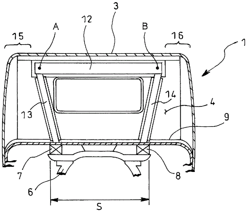
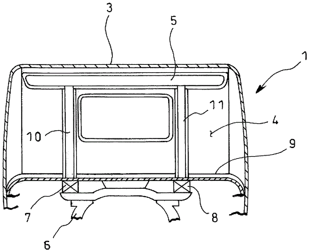
[0027] Figure 4 shows an example of the mode of carrying out the present invention, and gives the same image 3 Parts with the same reference numerals represent the same items.

[0028] exist Figure 4 In the example illustrated in the image 3 In the case of the conventional structure shown in the same, the wall surface of the indoor side of the backboard 4 of the cab 1 is installed with a reinforcement beam 12 and a reinforcement column 13, 14 for reinforcement, but with the backboard 4 top of the cab 1 as the slave vehicle The two parts where the outer end of the width direction enters the inner side with the required length are load support points A and B, and a pair of reinforcement columns 13 and 14 are installed on the aforementioned back plate 4 to be connected to support the aforementioned steering wheel from the frame 6 side. Between the bottom plate 9 di...


PUM


Abstract

The reinforcement structure of the present invention is based on the two parts of the upper part of the back panel (4) of the cab (1) entering from the outside end in the vehicle width direction to the inside as load support points (A, B), and a pair of reinforcement columns ( 13, 13) Install on the aforementioned back panel (4) so ​​as to be directly above the pair of rear cab brackets (7, 8) that support the rear of the aforementioned cab (1) from one side of the frame (6) Between the bottom plate (9) of the aforementioned load support points (A, B), and at the same time, the reinforcing beam (12) is installed on the aforementioned back plate (4) so ​​that the upper ends of the aforementioned reinforcing columns (13, 14) are connected to each other. For connection, non-reinforced portions are left as impact absorbing portions (15, 16) on both sides of the reinforcing beam (12) in the vehicle width direction.

Description

technical field [0001] The present invention relates to a cab reinforcement structure. Background technique [0002] In recent years, especially in Europe and other places, vehicle regulations have become more and more stringent. For example figure 1 As shown, for a flat-headed large truck, etc., it is planned to hit the upper side of the driver's cab 1 with the impact head 2, first give a side impact, and then figure 2 As shown, the upper surface of the roof panel 3 of the cab 1 is impacted with another impact head 2', and the strength test is a strength test in which a load is applied in the vertical direction. [0003] That is, the strength of the driver's cab 1 when this new strength test test rolls over, when actually rolling, since the driver's cab 1 is the state of rollover at first, after adding a side impact to the upper side of the driver's cab 1, Due to the further rolling, the cab 1 is in a bottom-up state (rolling 180°), and a load in the downward direction ...

Claims


Application Information

Patent Timeline
Patent Type & Authority Patents(China)
IPC IPC(8): B62D33/06B62D25/08
CPCB60R21/131B62D33/06B60R2021/137B62D21/157B62D21/15B62D33/063
Inventor 石灰伸好
Owner HINO MOTORS LTD
Why Eureka
Try Eureka