

Deformation processing method for optical aspheric element
A deformation processing, aspheric technology, applied in optical surface grinder, metal processing equipment, control of workpiece feed movement, etc., can solve the problems of long processing time and high cost, reduce processing cost, improve surface waviness error, The effect of shortening the processing time
- Summary
- Abstract
- Description
- Claims
- Application Information
AI Technical Summary
Problems solved by technology
Method used
Image

Examples
Embodiment Construction
[0025] The present invention will be described in further detail below in conjunction with the accompanying drawings.
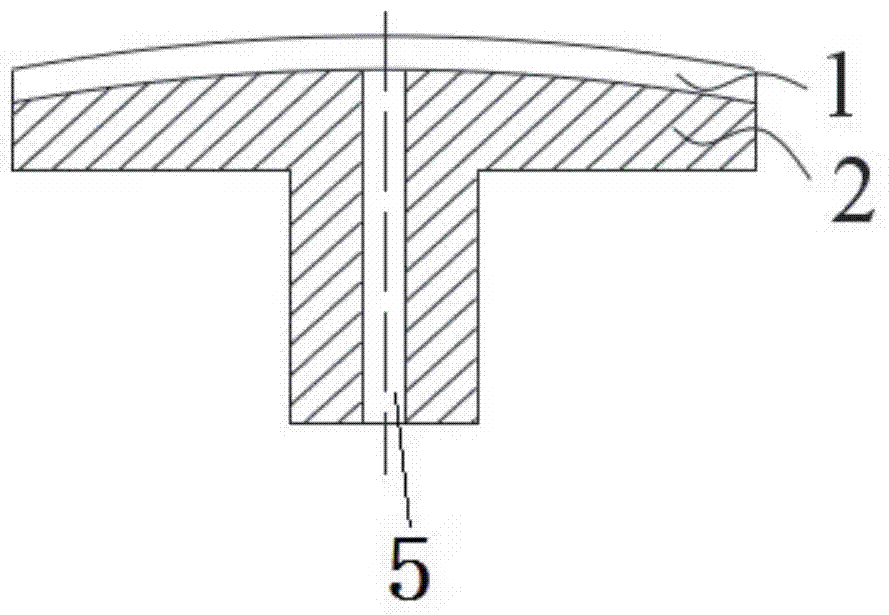
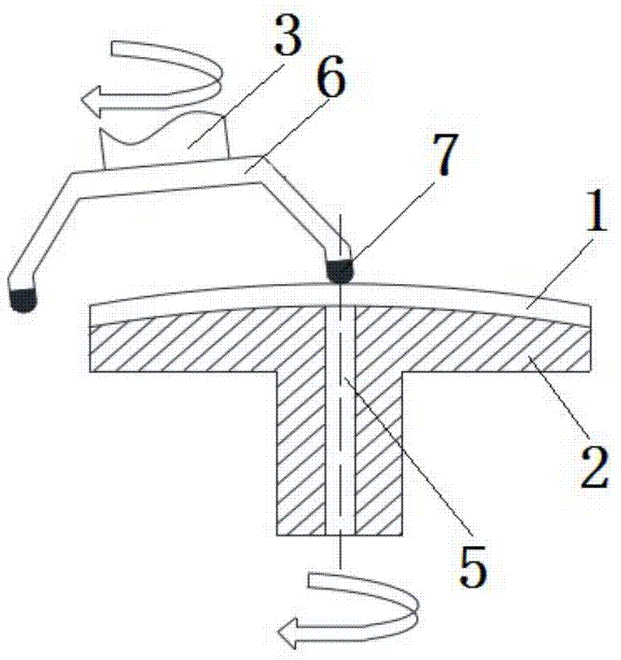
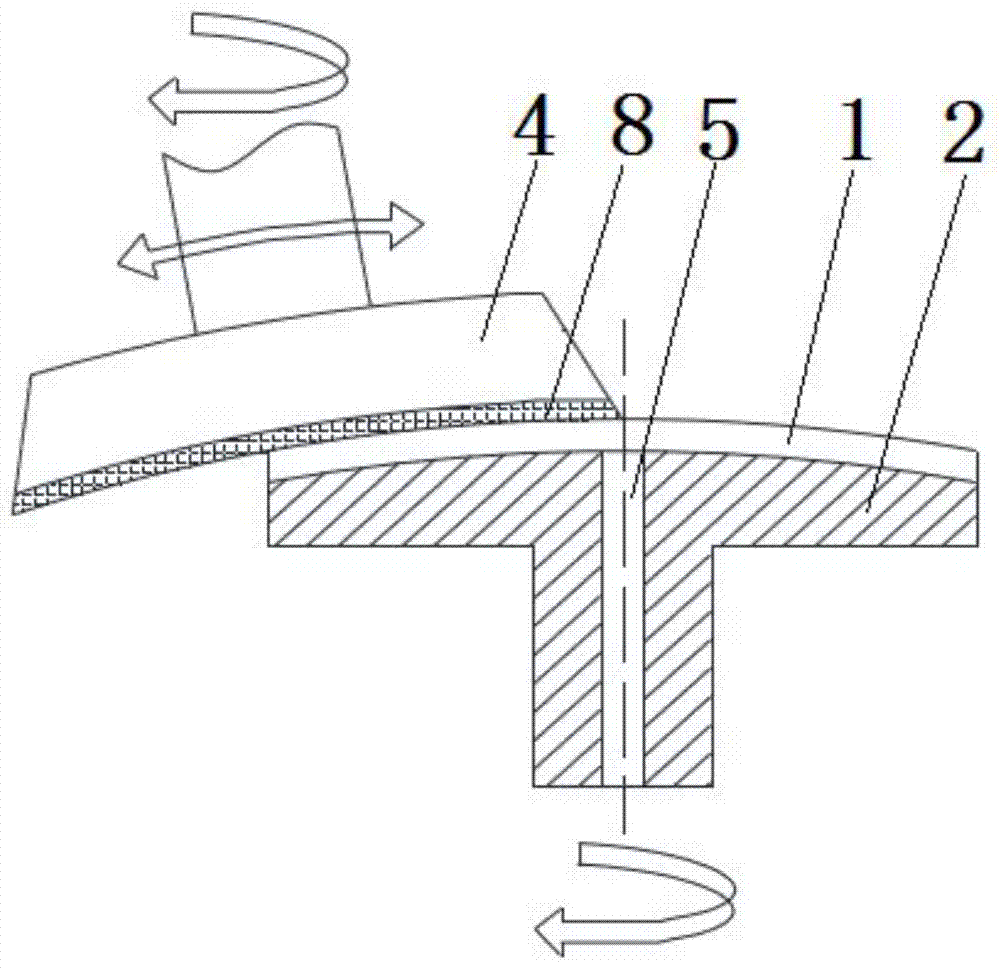
[0026] A deformation processing method of an optical aspheric element of the present invention is mainly realized through the following steps:
[0027] Step 1, the surface generatrix equation of the optical aspheric element 1, as shown in formula (1):
[0028] Z ( s ) = C s 2 1 + 1 - ( 1 + k ) C 2 s 2 + A 4 s 4 + ...
PUM
 Abstract
Description
Claims
Application Information