Flying 3D printing robot

A 3D printing and aircraft technology, applied in the field of flying robots, can solve the problems of multi-rotor unmanned aerial vehicle robots, etc., and achieve the effect of enhancing 3D printing efficiency, compact structure, and small volume

Inactive Publication Date: 2015-07-08
SHANGHAI UNIV
View PDF8 Cites 18 Cited by
  • Summary
  • Abstract
  • Description
  • Claims
  • Application Information

AI Technical Summary

Problems solved by technology

[0009] Although the above patents have been accepted in the field of robotics, and even some related products have appeared, there is no similar concept for multi-rotor unmanned aerial vehicle robots for 3D printing.

Method used


Image

  • Flying 3D printing robot
  • Flying 3D printing robot
  • Flying 3D printing robot

Examples


Embodiment 1

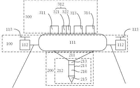
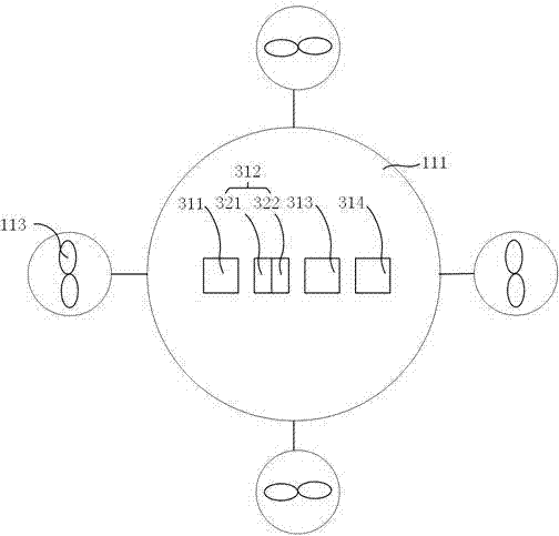
[0029] see figure 1 and figure 2 , a 3D printing robot capable of flying, comprising a multi-rotor unmanned aerial vehicle mechanism 100, a 3D printing mechanism 200, a feedback / communication / control circuit 300, the multi-rotor unmanned aerial vehicle mechanism 100 is fixedly connected to the 3D printing mechanism 200, and the multi-rotor unmanned aerial vehicle mechanism 100 is fixedly connected to the 3D printing mechanism 200. A feedback / communication / control circuit 300 is installed on the human aircraft mechanism 100 at the same time;

[0030] The multi-rotor unmanned aircraft mechanism 100 includes a casing 111, a motion motor 112, and a propeller 113. The motion motor 112 is installed on the casing 111, and the end is connected with the propeller 113.

[0031] The 3D printing mechanism 200 includes a connecting arm 211 and a printing head 212. The connecting arm 211 is fixed on the casing 111 of the multi-rotor unmanned aerial vehicle mechanism 100. The...

Embodiment 2

[0034] The technical solution of this embodiment is basically the same as that of Embodiment 1, the difference is that:

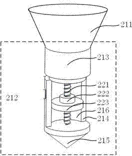
[0035] see image 3, in this embodiment, the 3D printing mechanism 200 should also include a rotating lead screw 221, an extruding nut 222, an extruding piston 223, and the feeding motor 213 is sequentially connected to the rotating lead screw 221, extruding nut 222, extruding piston 223, 3D The printing mechanism 200 is a piston syringe type extrusion feeding mechanism. The printing material 216 is pre-filled into the heating chamber 214, and the rotating screw 221 is driven by the feeding motor 213 to rotate, pushing the extrusion nut 222, and finally pushing the extrusion piston 223 to heat the The printing material 216 is extruded through the extrusion head 215 for 3D printing.

Embodiment 3

[0037] The technical solution of this embodiment is basically the same as that of Embodiment 1, the difference is that:

[0038] see Figure 4 , in this embodiment, the 3D printing mechanism 200 should also include a pulverizing gear 231, the feeding motor 213 is connected to the pulverizing gear 231, the 3D printing mechanism 200 is a motor gear meshing feeding mechanism, the printing material 216 is filamentous when it is not pulverized and heated, and is passed through the feeding The motor 213 drives the crushing gear 231 to rotate, pulverizes and pushes the heated printing material 216 to be extruded through the extrusion head 215 for 3D printing.


PUM


Abstract

The invention relates to a flying 3D printing robot. The flying 3D printing robot comprises an omni-directional mobile platform mechanism, a Z-axis elevating system, a 3D printing mechanism and feedback/communication/control circuits. The flying 3D printing robot is characterized in that the Z-axis elevating system is arranged on and fixedly connected with the omni-directional mobile platform mechanism; the 3D printing mechanism is arranged on and fixedly connected with the Z-axis elevating system; the feedback/communication/control circuits are all mounted on the omni-directional mobile platform mechanism; and the feedback/communication/control circuits control the omni-directional mobile platform mechanism and the Z-axis elevating system to drive the 3D printing mechanism to realize printing of three-dimensional long-strip objects without dimensional limits. The flying 3D printing robot has the characteristics of compact structure, a small size, exemption from dimensional limits on to-be-printed objects of traditional 3D printer, high movement flexibility and a fast printing speed; cooperation and communication among a plurality of printing robots are simultaneously realized, and 3D printing efficiency is further improved; and the flying 3D printing robot is especially applicable to low-cost and high-efficiency printing of great-distance long-strip objects like walls of buildings.

Description

technical field [0001] The invention relates to both the technical field of 3D printers and the technical field of flying robots, in particular to a flying 3D printing robot. Background technique [0002] 3D printer, also known as three-dimensional printer, is a kind of cumulative manufacturing technology, that is, a machine of rapid prototyping technology. It is based on a digital model file, using special wax, powdered metal or plastic and other bondable materials. Print layer by layer of adhesive material to create three-dimensional objects. At this stage, 3D printers are used to manufacture products, and the technology of constructing objects by layer-by-layer printing. [0003] Since 3D printing technology can be used in jewelry, footwear, industrial design, architecture, engineering and construction (AEC), automotive, aerospace, dental and medical industries, education, GIS, civil engineering, and many other fields. It is often used in mold manufacturing, industrial ...

Claims


Application Information

Patent Timeline
Patent Type & Authority Applications(China)
IPC IPC(8): B29C67/00
Inventor 张泉张记斐张金松
Owner SHANGHAI UNIV
Why Eureka
Try Eureka