Slag-blocking structure for automatic argon-blowing joint device

A joint device and automatic technology, applied in mechanical cleaning, manufacturing tools, metal processing equipment, etc., can solve problems such as dust accumulation and slag accumulation at the male end of the joint, reduce erosion, avoid dust and slag accumulation, and ensure use The effect of longevity

Active Publication Date: 2015-07-08
WUXI JULI HEAVY IND OFF
View PDF4 Cites 2 Cited by
  • Summary
  • Abstract
  • Description
  • Claims
  • Application Information

AI Technical Summary

Problems solved by technology

[0003] In view of the above problems, the present invention provides a slag-retaining structure of an automatic argon-blowing joint device, which can solve the problem of easy accumulation of slag and dust at the male end of the joint existing in the existing automatic argon-blowing joint device, and can effectively prevent high-temperature steel slag from splashing On the spring at the male end of the connector to ensure the service life of the spring

Method used


Image

  • Slag-blocking structure for automatic argon-blowing joint device
  • Slag-blocking structure for automatic argon-blowing joint device
  • Slag-blocking structure for automatic argon-blowing joint device

Examples


Embodiment Construction

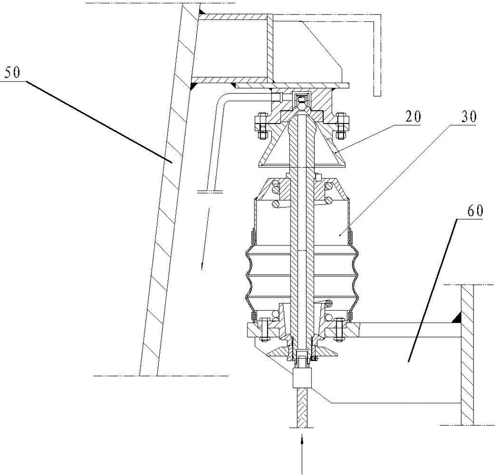
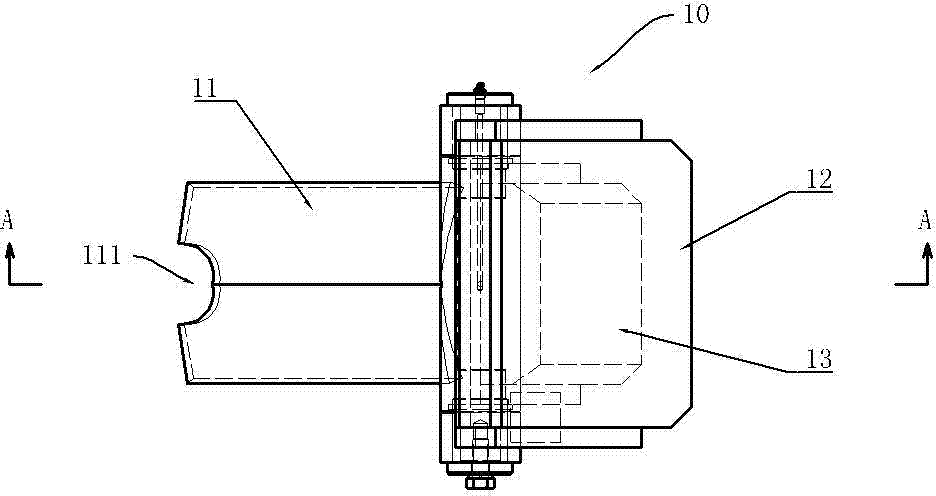
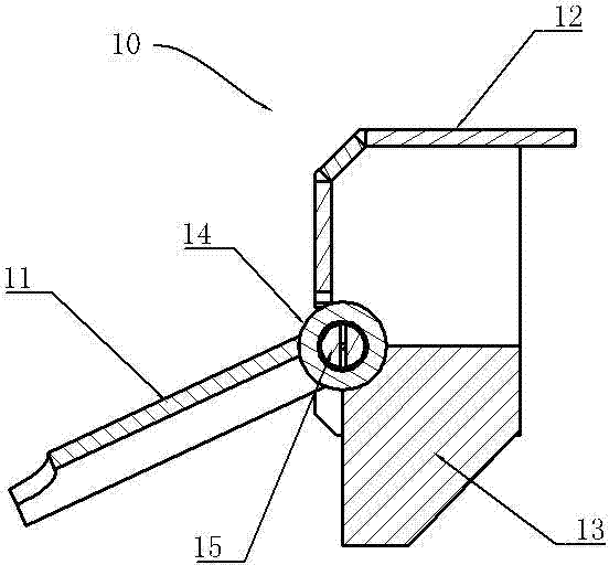
[0024] See Figure 2 ~ Figure 6 , the present invention includes a joint female end 20 and a joint male end 30 of the automatic argon blowing joint device, the joint female end 20 is installed on the tank wall of the molten steel tank, and the joint male end 30 is installed on the support 40 of the transfer equipment, which also includes The slag blocking device 10 installed on the bracket 40 of the transfer equipment, the slag blocking device 10 includes a rotatable slag blocking plate 11, a housing 12, a counterweight 13, a shaft sleeve 14 and a shaft 15, and a flange of the female end 20 of the joint A pressure plate 22 is installed on the bottom surface of the assembly 21, the slag retaining plate 11 and the counterweight 13 are fixedly installed on the outer peripheral surface of the shaft sleeve 14, the weight of the slag retaining plate 11 is less than that of the counterweight 13, and the housing 12 is installed on the bracket 40 of the rotating equipment , the front e...


PUM


Abstract

The invention provides a slag-blocking structure for an automatic argon-blowing joint device. The structure can overcome the problem of proneness to accumulation of slag and ash of a male joint terminal in conventional automatic argon-blowing joint devices, can effectively block high-temperature steel slag from splashing onto a spring of the male joint terminal and ensures service life of the spring. According to the invention, the slag-blocking structure comprises a female joint terminal and the male joint terminal of the automatic argon-blowing joint device, wherein the female joint terminal is arranged on the tank wall of a liquid steel tank, and the male joint terminal is arranged on a support of transloading equipment. The slag-blocking structure is characterized in that the slag-blocking structure further comprises a slag-blocking device installed on the support of the transloading equipment, and the slag-blocking device comprises a rotatable slag-blocking plate; when the female joint terminal and the male joint terminal of the automatic argon-blowing joint device are disconnected, the slag-blocking plate located right above the male joint terminal blocks high-temperature steel slag; and when the female joint terminal and the male joint terminal of the automatic argon-blowing joint device need to be connected, the slag-blocking plate can downward rotate so as to allow the joint body of the male joint terminal to be exposed and engaged with the joint body of the female joint terminal.

Description

technical field [0001] The invention relates to the field of auxiliary equipment in the steelmaking production process, in particular to a slag retaining structure of an automatic argon blowing joint device. Background technique [0002] During the molten steel transfer process under the furnace, the molten steel tank needs to blow argon to the molten steel to achieve the effect of stirring the molten steel. Generally, argon blowing devices are usually installed on the transfer equipment under the furnace, such as molten steel tank cars and ladle turrets. When the molten steel When the tank is dropped, it is necessary to connect the argon pipeline of the molten steel tank with the argon blowing device on the transfer equipment. At present, most of the docking operations are performed manually through quick-change joints. Due to the heat dissipation of the molten steel during transfer It will cause the precipitation of sulfur and phosphorus in the molten steel, resulting in t...

Claims


Application Information

Patent Timeline
Patent Type & Authority Applications(China)
IPC IPC(8): C21C7/072B22D43/00
Inventor 赵洪柱王凤良
Owner WUXI JULI HEAVY IND OFF
Why Eureka
Try Eureka