Pre-formed plastic water meter chamber and water meter mounting method

A technology for water meter wells and plastics, which is applied in water conservancy projects, measuring devices, underwater structures, etc., can solve the problems of poor load-bearing capacity, cannot be sealed together, heavy weight, etc., achieve good load-bearing capacity, reduce construction man-hours, light weight effect

Active Publication Date: 2015-07-08
ZHEJIANG BANGDE PIPE IND
View PDF6 Cites 3 Cited by
  • Summary
  • Abstract
  • Description
  • Claims
  • Application Information

AI Technical Summary

Problems solved by technology

[0004] The first purpose of the present invention is to provide a prefabricated plastic water meter well that can ensure strength and good load-bearing capacity with a lighter weight and appearance volume, which solves the problems existing in the existing prefabricated water meter wells. The problem of heavy weight and poor load-bearing capacity
[0005] The second object of the present

Method used


Image

  • Pre-formed plastic water meter chamber and water meter mounting method
  • Pre-formed plastic water meter chamber and water meter mounting method
  • Pre-formed plastic water meter chamber and water meter mounting method

Examples


Embodiment 1

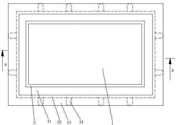
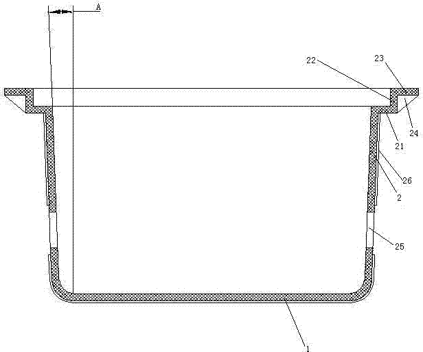
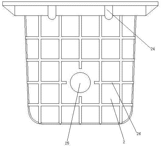
[0035] Embodiment one, see figure 1, a prefabricated plastic water meter well, comprising a bottom wall 1 and a side wall 2 connected to the bottom wall. The bottom wall 1 is a flat bottom structure. The side wall 2 is square tubular. Both the bottom wall 1 and the side wall 2 are made of plastic. The bottom wall 1 and the side wall 2 have an integral structure, that is, they are injection molded together. The upper end of the side wall 2 is turned outward to form a well cover bearing ring 21 , the radially outer end of the well cover bearing ring 21 is turned upward to form a well cover stop ring 22 , and the upper end of the well cover stop ring 22 is turned outward to form a booster ring 23 . Between the outer peripheral surface of the well cover limiting ring 22 and the lower end surface of the booster ring 23, several booster ribs 24 are arranged along the circumferential direction of the well cover limiting ring.

[0036] see figure 2 , The left and right ends of t...

Embodiment 2

[0039] Embodiment two, the difference with embodiment one is:

[0040] see Figure 5 , The pipe hole 25 is provided with a seal 6 . The sealing member 6 includes an elastic sealing tube 61 and a connecting ring 62 . The connecting ring 62 and the elastic sealing tube 61 are of an integral structure and are hermetically connected. The elastic sealing tube 61 is a reversible structure. The elastic sealing tube 61 extends toward the outside of the side wall 2 . The inner surface 611 of the elastic sealing tube is a conical surface. The outer surface 612 of the elastic sealing tube is a conical surface. The outer radius of one end of the elastic sealing tube 61 connected with the connecting ring is large, and the outer radius of the other end is small. One end of the elastic sealing tube 61 connected to the connecting ring has a large opening area, and the other end has a small opening area. There is an arc surface transition between the connecting ring 62 and the elastic s...

Embodiment 3

[0047] Embodiment three, the difference with embodiment two is:

[0048] see Figure 9 , also includes a water meter support plate 7. The water meter support plate 7 is supported on the inner surface of the bottom wall 1 by several support rods 9 . The water meter support plate 7 is disconnected with the side wall 2.

[0049] see Figure 10 , the support rod 9 is a tubular structure. The outer peripheral surface of the support rod 9 is provided with several shape-changing guide grooves 91 . The shape-changing guide grooves 91 are axially distributed along the support rod 9 . The inner peripheral surface of the support rod 9 is provided with several inner deformation guide grooves 92 . The inner deformation guide grooves 92 are axially distributed along the support rod 9 . Both the shape deformation guide groove 91 and the inner deformation guide groove 92 are annular grooves extending along the circumferential direction of the support rod 9 . The shape deformation guid...


PUM


Abstract

The invention relates to a water meter chamber. A pre-formed plastic water meter chamber comprises a bottom wall, and a tubular sidewall which is connected to the bottom wall, wherein pipe holes are formed in the sidewall; the bottom wall and the sidewall are manufactured from plastic and integrally structured; the sidewall is inclined by a manner that the upper end is outward; the upper end of the sidewall is outwards overturned to form a well lid bearing ring; the outer radial end of the well lid bearing ring is upwards overturned to form a well lid limiting ring; the upper end of the well lid limiting ring is outwards overturned to form an assisting ring. According to the pre-formed plastic water meter chamber and the water meter mounting method, high strength and bearing capacity can be ensured with light weight and small appearance size; the problems of large weight, poor bearing capacity and inconvenient sealing of the existing pre-formed water meter chamber can be solved.

Description

technical field [0001] The invention relates to a water meter well, in particular to a prefabricated plastic water meter well. Background technique [0002] When installing a water meter outdoors, it is necessary to construct a water meter well whose well cover is located on the ground and the well body is buried underground, and the water meter is installed in the water meter well. The original water meter wells were built on-site with bricks, so there were disadvantages of long construction period and high labor cost. In order to overcome the above-mentioned deficiencies of the water meter well of the brick structure, a water meter well in the form of a prefabricated part combining a steel structure with a concrete structure has been designed. A kind of existing prefabricated water meter well is disclosed in the Chinese Patent No. 2012205346498, the authorized announcement date is April 17, 2013, and the patent document titled "water meter well and water meter device ther...

Claims


Application Information

Patent Timeline
IPC IPC(8): E02D29/12E02D29/14G01F15/18
Inventor 胡德林
Owner ZHEJIANG BANGDE PIPE IND
Why Eureka
Try Eureka