Eureka AIR delivers breakthrough ideas for toughest innovation challenges, trusted by R&D personnel around the world.

Magnetic liquid magnetic induction intensity sensor

A technology of magnetic induction intensity and magnetic liquid, applied in the field of sensors, can solve the problems of intolerance to shock and vibration, high requirements for working conditions, and weak robustness. wide effect

Inactive Publication Date: 2015-07-08
BEIJING JIAOTONG UNIV
View PDF7 Cites 9 Cited by
  • Summary
  • Abstract
  • Description
  • Claims
  • Application Information

AI Technical Summary

Problems solved by technology

[0003] The technical problem to be solved by the present invention: the existing magnetic induction intensity sensor is not robust, not resistant to shock and vibration, and has high requirements for working conditions

Method used


Image

  • Magnetic liquid magnetic induction intensity sensor
  • Magnetic liquid magnetic induction intensity sensor

Examples


Embodiment Construction

[0015] to attach figure 1 And attached figure 2 The present invention will be further described for the specific embodiment:

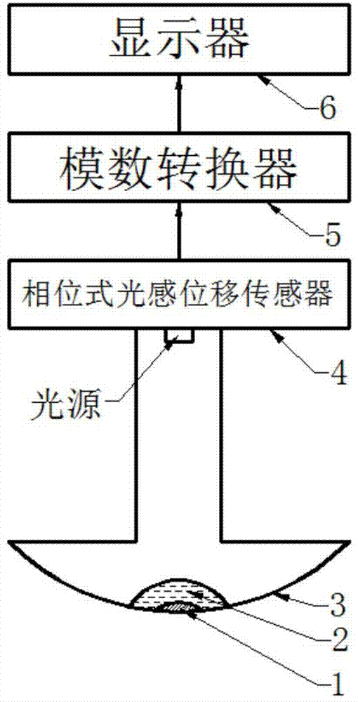
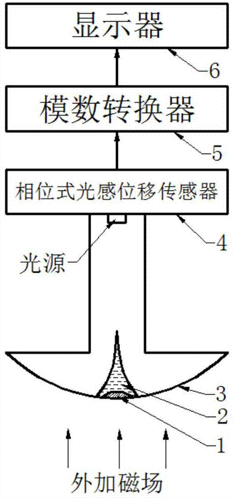
[0016] A sensor for the magnetic induction intensity of a magnetic liquid, the sensor comprising: a weak magnet 1, a magnetic liquid 2, a magnetic field probe 3, a phase type optical displacement sensor 4, an analog-to-digital converter 5, and a display 6.

[0017] Connections between the parts of the sensor:

[0018] Fix the weak magnet 1 at the center of the arc-shaped bottom surface of the magnetic field probe 3, and then inject the magnetic liquid 2 into the arc-shaped bottom surface of the magnetic field probe 3. The weak magnet 1 is used to absorb the magnetic liquid 2, so that the magnetic liquid 2 is always located in the magnetic field probe 3 at the center of the arc-shaped bottom surface. Then install the phase-type photosensitive displacement sensor 4 at the top of the magnetic field probe 3 facing the magnetic liquid 2, the light sourc...


PUM


Abstract

A magnetic liquid magnetic induction intensity sensor is suitable for magnetic induction intensity measurement. The sensor comprises a weak magnet (1), magnetic liquid (2), a magnetic field probe (3), a phase-shift light sensation displacement sensor (4), an analog-digital converter (5) and a display (6). In an initial state, the magnetic liquid (2) is located in the center of the bottom of the magnetic field probe (3) under the action of the weak magnet (1); after a magnetic field is applied, a peak is generated on the surface of the magnetic liquid (2), the larger the magnetic field intensity is, the higher the peak of the magnetic liquid (2) is, and the smaller the distance between the top of the peak of the magnetic liquid (2) and the light source of the phase-shift light sensation displacement sensor (4) is, so that the larger the output voltage signal is. In a certain range, a good linear relation exists between the input magnetic liquid (2) and the output voltage signal, and the requirements of engineering application can be met. The requirements for working conditions of the magnetic liquid magnetic induction intensity sensor is lower than that of a traditional sensor, the impact resistance and the vibration resistance are achieved, and the application range is wide.

Description

technical field [0001] The invention belongs to the field of sensors and is suitable for the measurement of magnetic induction intensity. Background technique [0002] At present, the commonly used methods for measuring magnetic induction mainly include: current balance method, force balance method, dynamics method, functional relationship method, magnetic deflection method, Hall effect method, electromagnetic induction method, etc. Among them, the most commonly used and mature method is the Hall effect method. The magnetic induction intensity sensor made by the Hall effect method is often called a Tesla meter or a Gauss meter. The accuracy of this kind of magnetic induction intensity sensor can meet the requirements of use, but its robustness is not strong. When it is impacted, the Hall probe is easily damaged. Once the Hall probe is bumped or vibrates, it will seriously affect the measurement accuracy. It needs to be returned to the factory for comparison. Standard magne...

Claims


Application Information

Patent Timeline
Patent Type & Authority Applications(China)
IPC IPC(8): G01R33/02
Inventor 李德才谢君
Owner BEIJING JIAOTONG UNIV
Why Eureka
Eureka Blog
Learn More