
Line scan apparatus, and method applied to the same

A technology of line scan and line scan camera, which is applied to parts of color TV, parts of TV system, TV, etc. It can solve the problems of distortion of the result image, failure to prevent the deviation of the conveyor speed change, etc., and reduce the image error Effect

Inactive Publication Date: 2015-07-08
HANWHA AEROSPACE CO LTD
View PDF10 Cites 5 Cited by
  • Summary
  • Abstract
  • Description
  • Claims
  • Application Information

AI Technical Summary

Problems solved by technology

[0009] For this reason, when only one of the two synchronous signals is used to obtain the image of the corresponding single inspection area, it cannot prevent the deviation of the speed change of the conveyor that provides the other synchronous signal.
[0010] Furthermore, on a conveyor line composed of multi-stage conveyors, if there is a step difference between conveyors or vibrations that differ between conveyors across the inspection area, the resulting image of the inspection area will be distorted.

Method used


Image

  • Line scan apparatus, and method applied to the same
  • Line scan apparatus, and method applied to the same
  • Line scan apparatus, and method applied to the same

Examples


Embodiment Construction

[0043] The advantages, features, and means for achieving the object of the present invention will be clarified by the accompanying drawings and the detailed description to be described later. However, the present invention is not limited to the embodiments described below and can be embodied in various forms. The following embodiments are intended to clarify the present invention and provide complete technical scope to those skilled in the art to which the present invention belongs. The protection scope of the present invention is determined only by the claims. Throughout the specification, the same symbols are attached to the same constituent elements.

[0044] Throughout the specification, the same symbols are attached to the same constituent elements. "And / or" includes each of the elements mentioned and all combinations of more than one.

[0045] The terms of ordinal numbers such as first and second are used to describe various elements, constituent elements, and / or parts...


PUM


Abstract

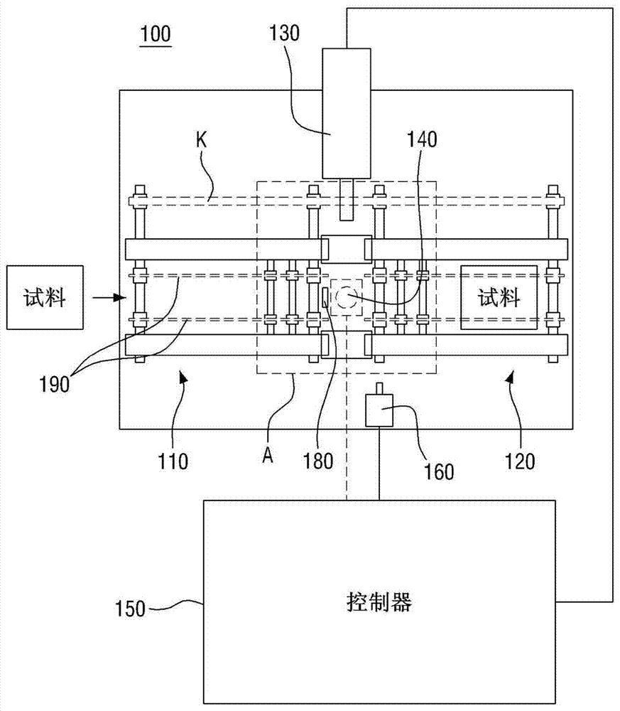
The invention provides a line scan apparatus, and a method applied to the same. More specifically, a transport line formed by a transport mechanism is provided with at least one examination area used for examining test portions. Thus, image errors when shooting an examination area can be remarkably reduced and modularized transport machine devices can be provided according to all examination areas.

Description

technical field [0001] The present invention relates to a line scanning device and a control method applicable to the device. More specifically, it relates to the ability to remarkably reduce photographic inspections when at least one inspection area for inspecting samples is provided on a conveying line composed of a conveyor. A line scan device for image error in the region and a control method applicable to the device. Background technique [0002] Usually, when an inspection area for inspecting samples is provided on a conveying line composed of conveying machines, a drive motor is attached to each conveying machine constituting the conveying line. [0003] Also, multiple drive motors mounted to each conveyor can run at different speeds. [0004] Since each drive motor runs at a different speed, the wire moves at a different speed between each conveyor. [0005] That is, in the inspection area located between the first conveyor moving at the first conveyor speed and th...

Claims


Application Information

Patent Timeline
Patent Type & Authority Applications(China)
IPC IPC(8): H04N1/028H04N1/04H04N5/235
CPCH04N1/00912H04N1/04H04N23/70A61M25/02A61M2025/028
Inventor 洪镇光李星宪
Owner HANWHA AEROSPACE CO LTD
Learn More