Audio rendering system

An audio and reproduction area technology, applied to stereo systems, electrical components, etc., can solve problems such as difficult implementation of computational complexity

Active Publication Date: 2015-07-08
HUAWEI TECH CO LTD
View PDF4 Cites 10 Cited by
  • Summary
  • Abstract
  • Description
  • Claims
  • Application Information

AI Technical Summary

Problems solved by technology

T.Betlehem, P.D.Teal described a convex-based Optimizing the method to achieve sound brightness contrast and sound field reconstruction, but the computational complexity of this method makes it difficult to implement in practical applications

Method used


Image

  • Audio rendering system
  • Audio rendering system
  • Audio rendering system

Examples


Embodiment Construction

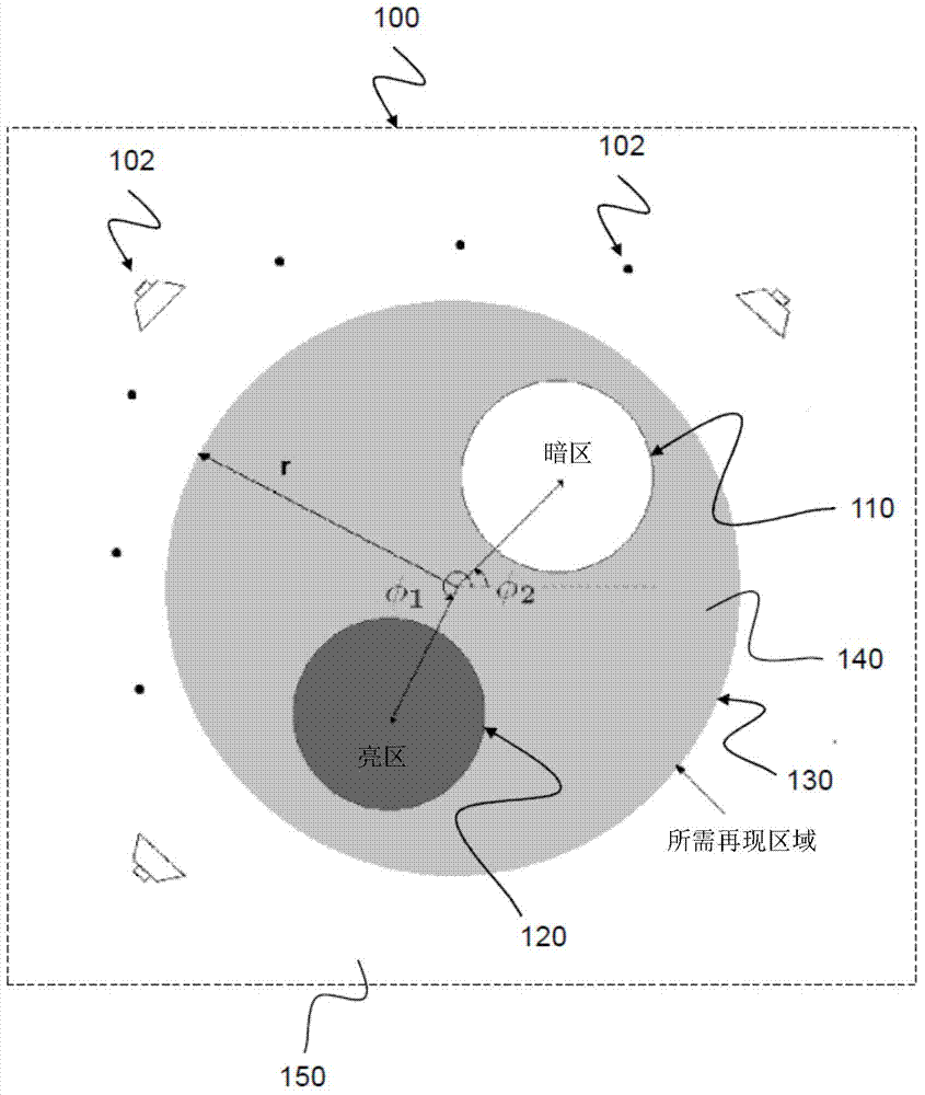
[0060] figure 1 A schematic diagram of an audio rendering system 100 according to an embodiment is shown.

[0061] exist figure 1 Among them, the desired reproduction area D130 is a general control circular area of ​​interest with a radius of r, which includes the acoustic circular bright area 120 and the circular dark area 110 . Regions with high acoustic brightness at specific frequencies are defined as bright regions 120, while the region with low acoustic brightness is Dark Zone 110. Relative to the center of the desired reproduction area 130, the bright area 120 and the dark area 110 are respectively defined by their angle Φ 1 and Φ 2 definition. It is ideal to set the acoustic energy density of the dark area 110 to zero, however, in practice, it is usually small relative to other areas. The remaining area of ​​the desired reproduction area 130 is defined as an uninhabited area 140 . The area outside the desired reproduction area 130 is defined as a leaky area 1...


PUM


Abstract

The invention relates to an audio rendering system (100), comprising: a plurality of loudspeakers (102) arranged to approximate a desired spatial sound field within a predetermined reproduction region (130), wherein the loudspeakers (102) are configured to approximate the sound field based on a weighted series of orthonormal basis functions for the reproduction region (130).

Description

Background technique [0001] The present invention relates to an audio presentation system such as an audio conferencing system and a method for sound field reproduction, in particular to a spatial multi-region sound field reproduction using a multi-loudspeaker arrangement. [0002] Multi-zone sound field reproduction is a method that aims to provide each listener with an independent sound environment without physically separating zones or using headphones. With the growing demand for personalized sound environments in the rapidly developing entertainment and communication fields, the spatial multi-area sound field reproduction over an extended area of ​​open space has been studied for the definition of multiple solutions, such as M.Poletti in 2008 "An investigation of 2D multizone surround sound system (An investigation of 2D multizone surround sound system)" in AES 125th General Audio Engineering Society Proceedings in 2011; IEEE ICASSP Proceedings by N.Radmanesh and I.S.Burn...

Claims


Application Information

Patent Timeline
Patent Type & Authority Applications(China)
IPC IPC(8): H04S7/00
CPCH04S2400/11H04S7/30H04S7/307
Inventor 金文宇威廉·巴斯蒂安·柯雷金大卫·维雷特
Owner HUAWEI TECH CO LTD
Why Eureka
Try Eureka