
Pipeline connecting structure

A connection structure and pipe body connection technology, applied in the direction of mechanical equipment, couplings, etc., can solve the problems of difficult alignment of the pipe part, unstable connection of the buckle part, poor airtightness of the pipe part, etc. Convenient and anti-deformation effect

Active Publication Date: 2015-07-15
ZHAOQING RIDE VALVE CO LTD
View PDF5 Cites 2 Cited by
  • Summary
  • Abstract
  • Description
  • Claims
  • Application Information

AI Technical Summary

Problems solved by technology

Because it is snapped after rotation, the operation of the entire buckle is inconvenient, and the small area of ​​the buckle makes the connection of the entire buckle part unstable. After long-term use, it will cause side deformation and slipping.
The pipe part and the pipe body fastening part of the existing pipe joint are in an active connection state, so that the airtightness of the pipe parts is very poor when they cooperate with each other, and it is not easy to align when the pipe parts are mated

Method used


Image

  • Pipeline connecting structure
  • Pipeline connecting structure
  • Pipeline connecting structure

Examples


Embodiment 1

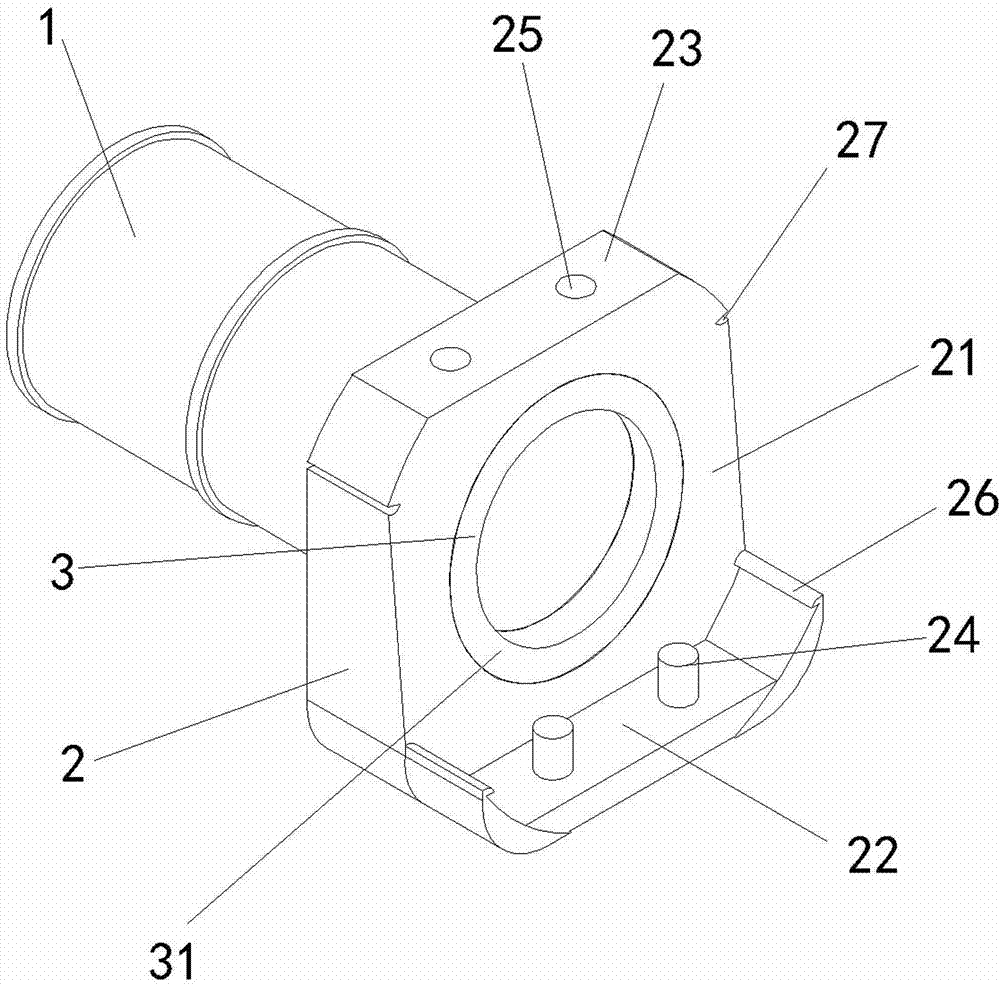
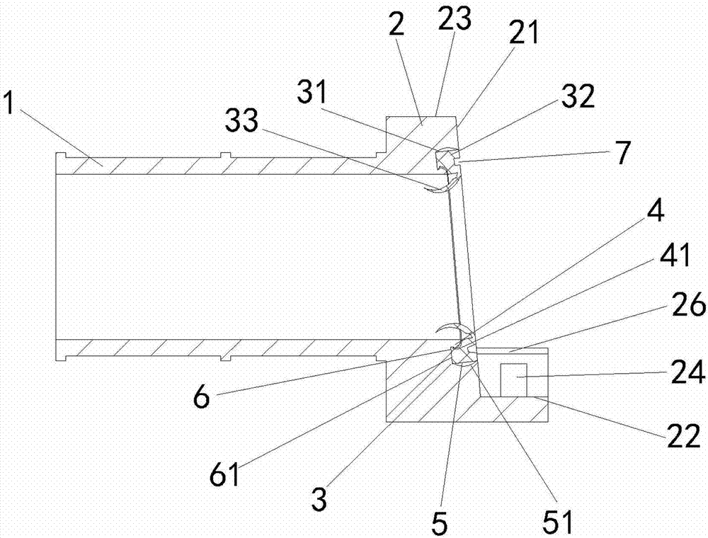
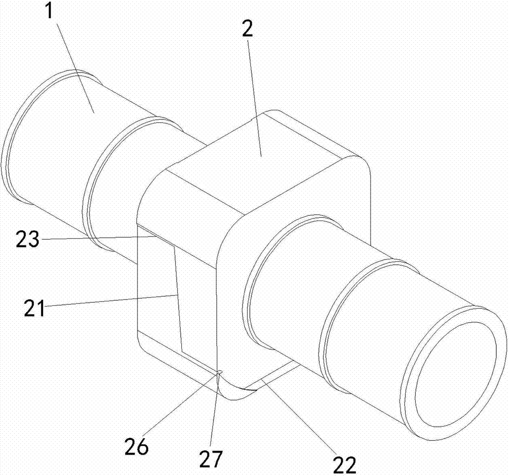
[0020] Embodiment one, such as figure 1 , figure 2 , image 3 , Figure 4 and Figure 5 A pipe connection structure shown includes a pipe body connection part 1 and a pipe head fastening part 2, the pipe body connection part 1 is used to connect rigid or flexible pipes, and the pipe head fastening part 2 is used to connect the other pipe The joint, the pipe head fastening part 2 is radially larger than the pipe body connecting part 1, the pipe head fastening part 2 includes an inclined pipe end joint surface 21, and the edge of the pipe end joint surface 21 is bent and connected to the joint part included in the pipe head buckle part 2 Moreover, the first limiting surface 22 and the second limiting surface 23 parallel to the axis of the tube body connecting portion 1 are fixedly connected to the tube body connecting portion 1 and the pipe head fastening portion 2 as a whole. The cross-section of the buckle part 2 of the pipe head is trapezoidal, and a second limiting surf...

Embodiment 2

[0025] In the second embodiment, a sealing part 3 is provided in the fastening part 2 of the pipe head, and the sealing part 3 includes an annular depression 31 and a seal that is installed in cooperation with the depression 31. The seal includes a seal body 32 disposed in the depression 31 and a flexible end The reversible tubular sealing auxiliary body 33 connected to the sealing body 32 , the free end of the sealing auxiliary body 33 can be turned over between the first limiting surface 22 side and the second limiting surface 23 side of the pipe end joint surface 21 . A sealing part 3 is provided in the buckle part 2 of the pipe head. The sealing part 3 includes an annular depression 31 and a sealing member fitted with the depression 31. The sealing member includes a sealing member body 32 arranged in the recess 31 and one end flexibly connected to the sealing member The reversible tubular sealing auxiliary body 33 of the body 32 , the free end of the sealing auxiliary body ...


PUM


Abstract

The invention relates to a pipeline connecting structure, and belongs to the technical field of pipeline connecting. The pipeline connecting structure comprises a pipe body connecting part and a pipe body buckling part, wherein the pipe body connecting part is used for connecting two pipelines, and the pipe body buckling part is used for sealing and connecting the pipe body connecting part; the matched surfaces of the pipe body buckling part comprise an inclined pipe end combining surface, a first limiting surface and a second limiting surface, and the first limiting surface and the second limiting surface are turned and connected at the edge of the pipe end combining surface, are parallel with the axis of the pipe body connecting part, and are arranged at the two opposite sides of the pipe end combining surface; a convex part is arranged at the first limiting surface, a concave part is arranged at a second limiting surface, a connecting line of matching tracks of the convex part and the concave part is parallel with the pipe end combining surface, and the matching tracks are vertical to the axis of a pipe body part. By adopting the technical scheme, the pipeline connecting structure has the advantages that the assembly is convenient, the fixing structure is firm, and the sealing property is good.

Description

technical field [0001] The invention belongs to the technical field of pipeline connection, in particular to a pipeline connection structure. Background technique [0002] At present, the pipe joints are engaged and rotated for clamping. This existing structure is only for clamping on the outer surface, and the contact area of ​​the clamping is relatively small. Because it is clamped after rotation, the operation of the entire buckle is inconvenient, and the small area of ​​the buckle makes the connection of the entire buckle part unstable. After long-term use, it will cause side deformation and slipping. The pipe part and the pipe body fastening part of the existing pipe joint are in a state of flexible connection, so that the airtightness of the pipe parts is very poor when they are mated with each other, and it is not easy to align when the pipe parts are mated. Contents of the invention [0003] The object of the present invention is to provide a pipeline connection s...

Claims


Application Information

Patent Timeline
Patent Type & Authority Applications(China)
IPC IPC(8): F16L37/12
CPCF16L37/12
Inventor 李卫国
Owner ZHAOQING RIDE VALVE CO LTD
Learn More