Condenser

A technology of a condenser and a body, applied in the field of refrigeration systems, can solve the problems of large size, high cost, and low condensation efficiency of the condenser, and achieve the effects of increasing the welding area, avoiding deformation problems, and improving condensation efficiency.

Inactive Publication Date: 2015-07-15
苏州东山昆拓热控系统有限公司
View PDF7 Cites 1 Cited by
  • Summary
  • Abstract
  • Description
  • Claims
  • Application Information

AI Technical Summary

Problems solved by technology

[0003] However, for the condenser with the above-mentioned structure, because the heat of the high-temperature gas or steam flowing in the tube body needs to be transferred to the tube body first, then the tube body transfers a heat dissipation shell, and then the heat dissipation shell transfers it to the surroundings. The air is finally discharged, and the heat of high-temperature gas or steam cannot be directly transferred to the air through the heat dissipation shell, so the condensation efficiency of this kind of condenser is very low, and generally the shape of the heat dissipation shell can only be enlarged by extending the length of the tube body To enhance its condensation effect, it is bulky and expensive

Method used


Image

  • Condenser
  • Condenser
  • Condenser

Examples


Embodiment

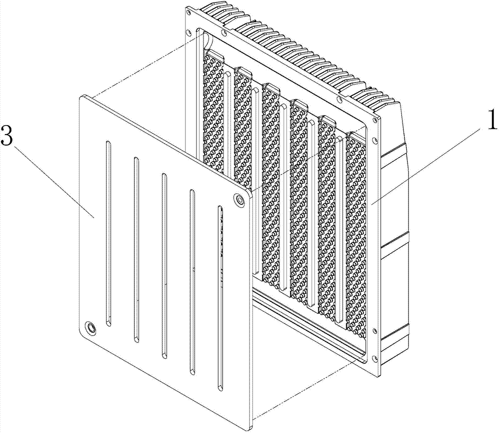
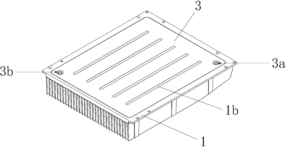
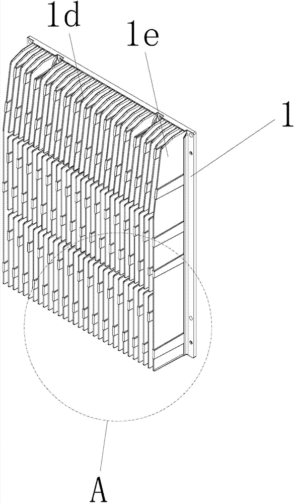
[0040] Example: Figure 1 to Figure 11A specific embodiment of the condenser of the present invention is shown, the condenser is mainly used in cabinet air conditioners, and it includes a condenser body 1 with an open cavity 2, on which the condenser body 1 is fixed and arranged A cover plate 3 at the opening of the open cavity 2 , and the cover plate 3 seals the open cavity 2 , thereby forming a closed cavity between the cover plate 3 and the condenser body 1 . The open cavity 2 is composed of a liquid inlet chamber 2a, a liquid outlet chamber 2b and a liquid outlet chamber 2c distributed sequentially from front to back. The cover plate 3 is provided with a liquid inlet hole 3a and a liquid outlet hole 3b communicating with the open cavity 2 (obviously, the liquid inlet hole 3a and the liquid outlet hole 3b are also formed by the cover plate 3 and the condenser body 1 The airtight cavity of the liquid is connected), specifically: the liquid inlet hole 3a communicates with th...


PUM


Abstract

The invention discloses a condenser. The condenser comprises a condenser body which is provided with an open cavity, wherein a cover plate which is arranged at an opening of the open cavity and is used for sealing the open cavity is fixedly arranged on the condenser body, the open cavity consists of a liquid inlet chamber, a liquid through chamber and a liquid outlet chamber which are sequentially distributed from front to back, a liquid inlet hole communicated with the liquid inlet chamber and a liquid outlet hole communicated with the liquid outlet chamber are formed in the cover plate, and a plurality of flow blocking bulges which are densely distributed in the liquid through chamber and are of staggered distribution are formed on the condenser body. The condenser disclosed by the invention is light and small in body type and extremely high in condensing efficiency.

Description

technical field [0001] The invention relates to the technical field of refrigeration systems, in particular to a condenser. Background technique [0002] In the prior art, the condensers used, especially the condensers used in cabinet air conditioners, are mostly tubular structures, which include a heat dissipation shell, and many curved tubes are installed in the shell. In specific applications, high-temperature gas or steam or pure liquid is passed into the liquid inlet hole in the tube. During the flow process, the high-temperature gas or steam in the tube body transfers heat to the tube body, and the tube body transfers heat to the heat dissipation shell. , the heat dissipation shell then transfers the heat to the surrounding air, thereby reducing the temperature of the high-temperature gas or steam in the pipe body, making it condensed and turning into a liquid with a lower temperature, which then flows out from the liquid outlet hole of the pipe body. Power plants use...

Claims


Application Information

Patent Timeline
Patent Type & Authority Applications(China)
IPC IPC(8): F25B39/04
CPCF25B39/04F25B2339/04
Inventor 刘明国
Owner 苏州东山昆拓热控系统有限公司
Why Eureka
Try Eureka