Gas-liquid separation for compressed air method and device

A gas-liquid separation device and gas-liquid separation technology are applied in separation methods, dispersed particle separation, chemical instruments and methods, etc., to achieve the effects of excellent gas-liquid separation, increase residence time, and improve condensation efficiency

Inactive Publication Date: 2003-09-03
孙永勇 +1
View PDF0 Cites 13 Cited by
  • Summary
  • Abstract
  • Description
  • Claims
  • Application Information

AI Technical Summary

Problems solved by technology

[0006] In order to overcome the above-mentioned shortcomings of existing high-pressure air flowing through air-cooled air dryers to remove moisture in the air, the present invention provides a method and device for gas-liquid separation of compressed air, which uses water cooling and air pressure release The formed natural cooling phenomenon cools the high-pressure air without consuming power, and avoids the situation that the gas-liquid separation cannot be performed once the air-cooled dryer fails in the prior art. By increasing the diameter of the cooling pipe, Make the high-pressure air enter the large space from the small space, and then form a decompression phenomenon, let the air cool down due to decompression, and increase the residence time of the high-pressure air in the cooling barrel, coupled with the cooling effect of the coolant, so that in the multiple functions To improve the condensation effect of the cooling barrel, when the high-pressure air enters the gas-liquid separation barrel, the pressure will drop to the dew point temperature, causing a large amount of water vapor to condense, thus achieving an excellent gas-liquid separation effect

Method used


Image

  • Gas-liquid separation for compressed air method and device
  • Gas-liquid separation for compressed air method and device
  • Gas-liquid separation for compressed air method and device

Examples


Embodiment Construction

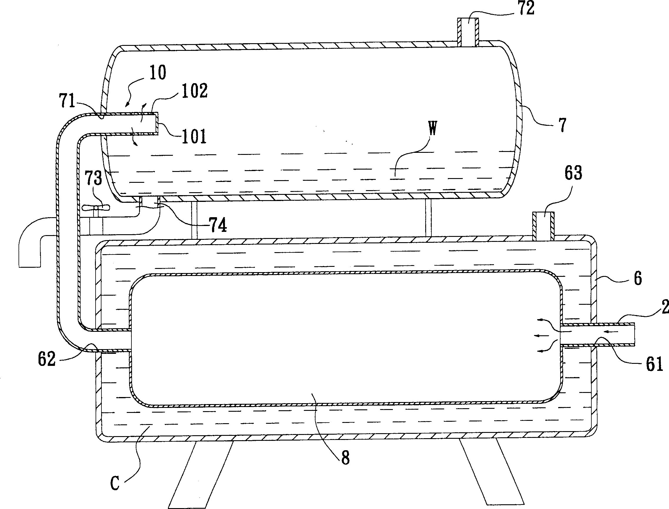
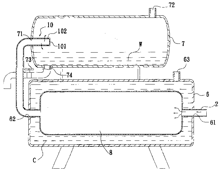
[0022] see figure 1 The embodiment of the gas-liquid separation device used in the present invention includes an airtight cooling barrel 6 and an airtight gas-liquid separation barrel 7, the cooling barrel and the gas-liquid separation barrel are horizontal, and the gas-liquid separation barrel 7 is Placed on the upper side of the cooling bucket 6.

[0023] The top of the cooling barrel 6 has a water injection port 63 through which the cooling liquid is injected into the cooling barrel. In this embodiment, the cooling liquid is water at normal temperature. There is an inlet 61 and an outlet 62 at both ends of the cooling drum respectively, and the inlet 61 is connected with an air compressor (not shown) by a delivery pipe 2, and a connecting pipe is connected between the inlet 61 and the outlet 62 in the cooling drum 6 . A cooling pipe 8 with a large diameter and extending straight.

[0024] One end of the gas-liquid separation barrel 7 has an air inlet 71, and the top of th...


PUM


Abstract

An air-water separating process for compressed air features that compressed air is delivered via delivering pipe into cooling pipe in cooling drum to release its pressure as the diameter of cooling pipe is greater than that of delivering pipe, so its temp is lowered to make the pressure of water vapour close to saturated vapour pressure. The cooled air is delivered in air-water separator where its pressure is further released and its temp is further lowered, so the water vapour is condensed. Its apparatus is composed of a cooling drum with cooling pipe in it and an air-water separator.

Description

technical field [0001] The invention relates to a gas-liquid separation method and device for compressed air. Background technique [0002] When a general factory uses pneumatic tools on the production line, it usually injects high-pressure air into the pneumatic tools for use. However, high-pressure air is prone to produce moisture under high heat conditions. If the air injected into the pneumatic tool contains moisture, the moisture will easily remain in the pneumatic tool, causing the internal parts of the pneumatic tool to rust, and even affecting the quality of the pneumatic tool. and operational effects. [0003] Therefore, first let the high-pressure air flow through an air-cooled dryer, remove the moisture in the air with the help of the cooling and dehumidification effect of the air-cooled dryer, and then spray the dehydrated air into the pneumatic tool to be used to avoid air tools Damaged by the moisture contained in the air and increases its lifespan. [0004]...

Claims


Application Information

Patent Timeline
Patent Type & Authority Applications(China)
IPC IPC(8): B01D5/00B01D53/26
Inventor 孙永勇陈全钦
Owner 孙永勇
Why Eureka
Try Eureka