Circuit

A circuit, current technology, applied in logic circuits, electrical components, pulse technology, etc.

Inactive Publication Date: 2015-07-15
沈兆英
View PDF0 Cites 0 Cited by
  • Summary
  • Abstract
  • Description
  • Claims
  • Application Information

AI Technical Summary

Problems solved by technology

This generates unnecessary power dissipation when the load is not drawing this maximum current

Method used


Image

  • Circuit
  • Circuit
  • Circuit

Examples


Embodiment Construction

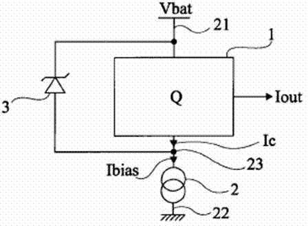
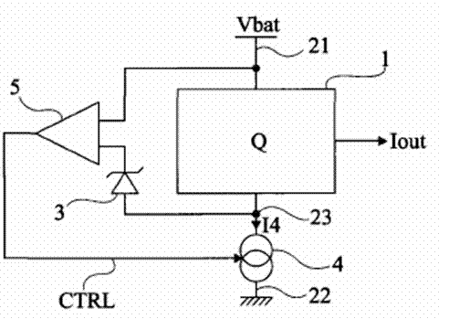
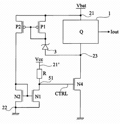
[0059] The same elements are labeled with the same reference numerals in different figures. For clarity, only those elements that are useful for understanding the described embodiments are shown and will be detailed. In particular, such embodiments are compatible with any type of load intended to be connected in series with a current source.

[0060] An example of application of the embodiment to be described is directed to a load formed by a charge pump or a charge transfer circuit. In such circuits, the power consumption varies according to the power consumption of the components powered by the charge pump.

[0061] Similar problems generally arise whenever a load is to be supplied from a variable voltage and it is desired to set its supply voltage by means of Zener diodes or the like. In effect, the load is then connected in series with a current source which creates a node at floating potential. For example, this could be an amplification or comparison circuit reference...


PUM


Abstract

The invention provides a circuit which comprises a current source which is serially connected with a load between two terminals of application of first direct-current voltage, an element is used for limiting the voltage spanning the load, and the circuit is used for controlling the value of current in the current source by using current flowing in the element. Due to the adoption of the circuit, the power consumption of the current source for supplying power to the load can be optimized, and the load to be supplied with power does not need to be modified.

Description

technical field [0001] The present application relates to electronic circuits and, in particular embodiments, to circuits for powering a load from a variable DC voltage. Background technique [0002] When a load is to be powered at a fixed DC voltage, a voltage setting element is often used, typically a Zener diode connected in parallel with the load. A current source is then connected in series with this parallel combination and powers the assembly with a DC voltage. Zener diodes have the function of limiting (setting) the voltage across the load. The current source has the function of sinking the current flowing through the load as well as through the Zener diode. [0003] For a fixed load (constant power dissipation), the current source is sized from this current to keep the Zener diode permanently in avalanche (acting as a voltage limiter). [0004] However, for loads with variable power consumption, the current source must be sized according to the maximum power cons...

Claims


Application Information

Patent Timeline
Patent Type & Authority Applications(China)
IPC IPC(8): H03K19/094
Inventor 沈兆英
Owner 沈兆英
Why Eureka
Try Eureka