System and method for utilizing flue gas waste heat

A technology of flue gas waste heat and flue gas temperature, which is applied in the direction of reducing greenhouse gases, climate sustainability, lighting and heating equipment, etc. In terms of design requirements and large footprint, it can reduce the risk of low-temperature corrosion, optimize energy conservation and emission reduction, and improve the efficiency of electrostatic precipitators.

Active Publication Date: 2019-03-29
龙净能源发展有限公司
View PDF8 Cites 0 Cited by
  • Summary
  • Abstract
  • Description
  • Claims
  • Application Information

AI Technical Summary

Problems solved by technology

However, the method of reducing the inlet water temperature will bring the risk of low-temperature corrosion of the equipment. Corrosion and ash blocking will make the heat transfer efficiency of the heat exchange tube row fail to meet the design requirements, causing the equipment to fail to meet the use requirements. The method of water temperature will cause problems such as large equipment resistance, high investment cost, and large floor space.
[0012] According to the above analysis, when the parallel flue gas waste heat utilization system and method are used, when the water side resistance of the flue gas waste heat utilization device system is greater than the water side resistance of the parallel N low pressure heater, the condensation at the outlet of the flue gas waste heat utilization device The water cannot be returned to the N-1 low-pressure heater, and the normal operation of the flue gas waste heat utilization device cannot be realized
[0013] The key problem to be solved by the present invention is that the temperature and quantity of water entering the flue gas waste heat utilization device in the traditional parallel process method cannot be changed randomly according to the load, season, and coal combustion, resulting in the temperature of the heat exchange tube wall of the flue gas waste heat utilization device being too low, resulting in Problems of low temperature corrosion and ash accumulation
Since the traditional parallel process method cannot effectively control the temperature and water volume of condensate entering the flue gas waste heat utilization device, it cannot meet the needs of the flue gas waste heat utilization device for the deep temperature adjustment treatment of the low-low temperature electrostatic precipitator and when the water side resistance of the flue gas waste heat utilization device is greater than When the water side resistance of No. N low-pressure heater, the flue gas waste heat utilization device cannot work normally, so the traditional parallel system and process method need to be improved urgently

Method used


Image

  • System and method for utilizing flue gas waste heat
  • System and method for utilizing flue gas waste heat
  • System and method for utilizing flue gas waste heat

Examples


Embodiment Construction

[0034] In order to enable those skilled in the art to better understand the solution of the present invention, the present invention will be further described in detail below in conjunction with the accompanying drawings and specific embodiments.

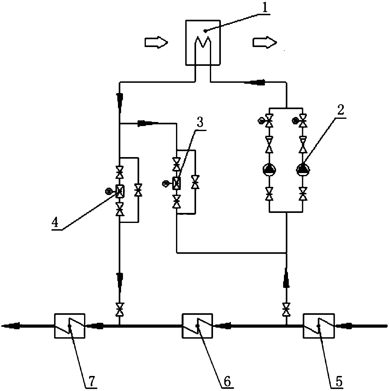
[0035] Please refer to image 3 , image 3 It is a schematic diagram of the pipeline and composition of a specific embodiment of the flue gas waste heat utilization system provided by the present invention

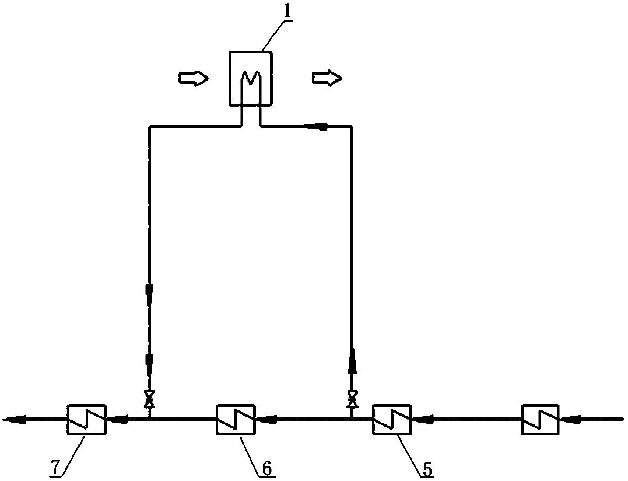
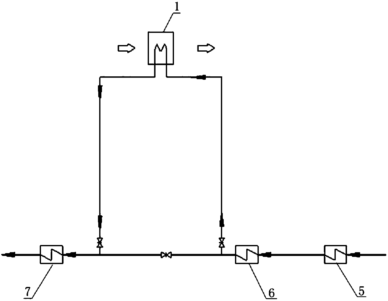
[0036]In a specific embodiment, the flue gas waste heat utilization system provided by the present invention is mainly composed of the first low-pressure heater 5 (that is, No. N+1 low-pressure heater, here is the shaft seal heater), the second low-pressure heater 6 (i.e. No. N low-pressure heater), the third low-pressure heater 7 (i.e. No. N-1 low-pressure heater), booster pump group 2, recirculation regulating valve group 3, return water regulating valve group 4 and flue gas waste heat Utilize device 1 etc. to connect throug...


PUM


Abstract

The invention discloses a flue gas waste heat utilization system and method. The flue gas waste heat utilization system comprises a first low-pressure heater (5), a second low-pressure heater (6), a third low-pressure heater (7) and a flue gas waste heat utilization device (1), wherein the first low-pressure heater (5), the second low-pressure heater (6) and the third low-pressure heater (7) are sequentially connected in series; the flue gas waste heat utilization device (1) is connected with the second low-pressure heater (6) in parallel; a booster pump unit is arranged between the water side inlet of the flue gas waste heat utilization device (1) and an outlet of the first low-pressure heater (5); a water return adjusting valve unit is arranged between the water side outlet of the flue gas waste heat utilization device (1) and an inlet of the third low-pressure heater (7); and a recirculation adjusting valve unit is arranged between an inlet of the water return adjusting valve unit and an inlet of the booster pump unit. The system and method can effectively reduce flue gas-dust specific resistance, improve the efficiency of an electrostatic precipitation, recycle flue gas waste heater, save coal consumption of a unit, save the occupied space of equipment, remove SO3 in flue gas efficiently, and relieve equipment corrosion of the flue gas waste heat utilization device.

Description

technical field [0001] The invention relates to the technical field of waste heat utilization of flue gas at the boiler tail of a coal-fired unit, and specifically relates to a waste heat utilization device for flue gas, a No. N+1 low-pressure heater, a No. N low-pressure heater, and a No. N-1 low-pressure heater. A parallel flue gas waste heat utilization system for recovering flue gas waste heat in a coal-fired power plant and a process method thereof. Background technique [0002] Due to fluctuations in coal combustion and unit aging, the actual exhaust gas temperature in active coal-fired power plants exceeds the design exhaust temperature, resulting in a series of problems such as a decrease in unit economy, a decrease in the efficiency of the electrostatic precipitator, and an increase in desulfurization water consumption. [0003] In recent years, the low and low temperature electrostatic precipitator technology based on the flue gas waste heat utilization device has ...

Claims


Application Information

Patent Timeline
Patent Type & Authority Patents(China)
IPC IPC(8): F23J15/06
CPCF23J15/06Y02E20/30
Inventor 张瑾谢庆亮林翔黄举福廖增安
Owner 龙净能源发展有限公司
Why Eureka
Try Eureka