
Electronic equipment configuration method and system

A technology of electronic equipment and a configuration method, which is applied in the electronic field and can solve problems such as unsatisfactory

Inactive Publication Date: 2015-07-15
LENOVO (BEIJING) CO LTD
View PDF7 Cites 8 Cited by
  • Summary
  • Abstract
  • Description
  • Claims
  • Application Information

AI Technical Summary

Problems solved by technology

[0006] The embodiment of the present application provides a method and system for electronic device configuration to solve the problem that existing methods in the prior art for automatic deployment in a server environment cannot satisfy the dynamic differentiation between server nodes in a multi-server deployment scenario. The technical problem of configuration requirements enables the deployment template to be customized according to the function type of each server node, so as to meet the configuration requirements of dynamic differentiation between server nodes in a multi-server deployment scenario.

Method used


Image

  • Electronic equipment configuration method and system
  • Electronic equipment configuration method and system
  • Electronic equipment configuration method and system

Examples


Embodiment 1

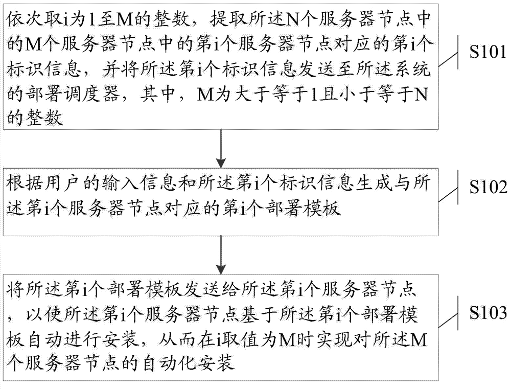
[0080] Please refer to figure 1 , the embodiment of the present application provides a method for configuring electronic equipment, which is applied to a server integration system, such as a large-scale data center or cloud computing environment system, and the system includes N server nodes, where N is greater than or equal to 1 integer, the method comprising the steps of:

[0081] S101: Take i as an integer from 1 to M in turn, extract the i-th identification information corresponding to the i-th server node among the M server nodes among the N server nodes, and send the i-th identification information To the deployment scheduler of the system, wherein M is an integer greater than or equal to 1 and less than or equal to N;

[0082] S102: Generate an i-th deployment template corresponding to the i-th server node according to user input information and the i-th identification information;

[0083] S103: Send the i-th deployment template to the i-th server node, so that the i...

Embodiment 2

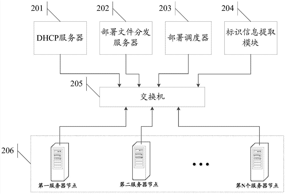
[0128] Based on the same inventive concept, the embodiment of this application also provides a system for configuring electronic equipment, please refer to figure 2 , including:

[0129] Identification information extraction module 204, deployment scheduler 203, deployment file distribution server 202 and N server nodes 206, N is an integer greater than or equal to 1; wherein,

[0130] The identification information extraction module 204 is configured to sequentially take i as an integer from 1 to M, extract the i-th identification information corresponding to the i-th server node of the M server nodes in the N server nodes 206, and The i-th identification information is sent to the deployment scheduler of the system, where M is an integer greater than or equal to 1 and less than or equal to N;

[0131] The deployment scheduler 203 is connected to the identification information extraction module 204, and is configured to receive the i-th identification information, and gener...


PUM


Abstract

The application discloses an electronic equipment configuration method and system, and aims to solve the technical problem that the demand of dynamic differential configuration among server nodes in a multi-server deployment scene cannot be met in a method applied to server environment automatic deployment in the prior art. The method comprises the following steps: setting i as an integer ranging from 1 to M in sequence, extracting ith identification information corresponding to an ith server node in M server nodes of N server nodes, and transmitting the ith identification information to a deployment scheduler; generating an ith deployment template corresponding to the ith server node according to the input information of a user and the ith identification information; and transmitting the ith deployment template to the ith server node in order that the ith server node is installed automatically based on the ith deployment template, so that automatic installation of the M server nodes is realized when i is M.

Description

technical field [0001] The present application relates to the field of electronic technology, and in particular to a method and system for configuring electronic equipment. Background technique [0002] In large-scale server systems (such as cloud computing systems), the operation of software is based on the underlying server environment, and the efficiency of server environment deployment often affects the development and launch cycles of software products. In a large-scale data center or cloud computing environment, there are many server nodes and complex management. Before each server is officially put into use, a lot of deployment work needs to be done, such as operating system installation, network resource configuration, software deployment, service customization, etc.; at the same time, for the convenience of operation and maintenance management, server deployment also needs to meet some specific dynamics Configuration requirements, for example, set the host name of ...

Claims


Application Information

Patent Timeline
IPC IPC(8): H04L12/24H04L29/12
Inventor 韩晓磊高瞻
Owner LENOVO (BEIJING) CO LTD
Learn More