Liner for reinforcing a pipe and method of making the same
A technology for lining and pipes, applied in the field of linings for strengthening pipes and its manufacture, which can solve the problems of expensive, time-consuming, difficult pipe replacement, etc.
Active Publication Date: 2015-07-15
OWENS CORNING INTELLECTUAL CAPITAL LLC
6 Cites 6 Cited by
AI-Extracted Technical Summary
Problems solved by technology
Such repairs often require the replacement of a length of pipe, as repairs to small sections of pipe by welding, patching, or other methods are often unsatisfactory, and because the diameter of the pipe do...
Method used
[0059] Another surface finish characteristic possessed by the yarn layer 302 is the formation of a protective layer that can be lost during use (eg, by abrasion) without affecting the structural properties of the lined pipe. The protective layer obtained through the use of the yarn layer 302 is more resistant to wear than constructions without the yarn layer 302, resulting in a lower wear rate (weight loss) of the cured liner 300. Thus, the protective layer is a sacrificial layer that provides enhanced abrasion and abrasion resistance to further protect the underlying reinforcing fabric layer 304 .
[0068] The reinforcement layers 310, 312 are bonded, coupled or otherwise bonded to each other. In an exemplary embodiment, reinforcement layers 310, 312 are stitched together by stitching element 318 (see FIG. 3). Stitching elements 318 are stitched or woven through the reinforcement layers 310, 312 to secure the reinforcement layers together. The seaming elements 318 are flexible to enhance the stretch and flexibility of the fabric layer 304 and thereby enhance the stretch and flexibility of the reinforced liner 300 as well. The seaming elements may be made of elastic or rubber-type materials. In an exemplary embodiment, stitching elements 318 are elastic yarns or the like. In an exemplary embodiment, stitching elements 318 are non-stretchable polyester yarns or other stretcha...
Abstract
A reinforced liner and methods of manufacturing the liner are disclosed. The liner includes a glass veil layer as an innermost layer in combination with an outer reinforcing layer that includes glass fibers. The glass veil layer and the reinforcing layer are joined together, such as by an elastic yarn. Inclusion of the glass veil layer imparts desirable surface finish characteristics to the reinforced liner.
Application Domain
Layered productsPipe elements +2
Technology Topic
YarnGlass fiber +1
Image
Examples
- Experimental program(1)
Example Embodiment
[0046] Although the broad inventive concept allows many different forms of embodiments, the content shown in the drawings and described herein in detailed specific embodiments is based on the understanding that this specification is regarded as an example of the broad inventive concept . Therefore, the broad inventive concept is not limited to the specific embodiments described here.
[0047] Unless otherwise defined, the terms used herein are the same as those commonly understood by those of ordinary skill in the technical field, and both include broad inventive concepts. The terms used herein are only used to describe example embodiments of the broad inventive concept, and do not limit the broad inventive concept. When used in the description of the broad inventive concept and the appended claims, the singular form "a" and "the" also include the plural form, unless the context clearly dictates otherwise.
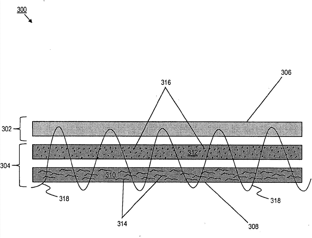
[0048] According to an example embodiment, image 3 A reinforced liner 300 with improved inner surface properties is shown.
[0049] Such reinforced liners typically include a series of reinforcement members oriented in a circumferential direction perpendicular to the longitudinal axis of the liner. These reinforcing members are arranged around the circumference of the liner and provide radial strength and rigidity to the liner after the liner has cured and solidified. The reinforcement members are typically filamentous elements, such as glass fibers.
[0050] The reinforced liner may also provide support in its longitudinal direction, in particular, the liner may include reinforcement members oriented along its longitudinal axis. These reinforcing members are usually filamentary elements, such as glass fibers.
[0051] Before curing, the reinforced lining should be flexible in the radial direction, and the reinforced lining should have sufficient rigidity after curing. The flexibility in the radial direction allows the reinforcing liner to expand in the radial direction to press against the inner wall of the damaged pipe. Different pipes (and damaged areas) may have different cross-sectional shapes and contours. Therefore, when the liner is inserted and cured, the reinforced liner may not have a continuous inner diameter and outer diameter along its length.
[0052] Glass fiber has relatively poor ductility characteristics. Therefore, a reinforced liner with continuous glass fibers oriented in the radial direction of the liner has a limited radial expansion capability. Therefore, the broad inventive concept includes the manufacture of reinforced fabrics that are stretchable in the warp, weft, or both directions. The fabric is easily inserted into the main pipe after being transformed into a hose shape and easily expands to conform to the diameter of the damaged pipe.
[0053] The example liner embodies these principles, and the reinforced liner 300 of one of such examples includes one or more layers of reinforcing fabric. In an exemplary embodiment, the fabric layer includes a fabric having continuous fibers oriented along the length of the liner and discontinuous fibers oriented generally perpendicular to the length of the liner. Different fibers are joined together to form a fabric. Discontinuous fibers have flexibility and hoop strength in the radial or circumferential direction of the liner. The lining is formed by overlapping strips of fabric. For example, the overlapping tape may be spirally wound, circumferentially wound, or placed as a longitudinally overlapping tape.
[0054] The broad inventive concept includes a variety of these reinforcing fabrics. Some example embodiments of such fabrics are described in US patents 6,360,780 (patent '780) and 6,615,875 (patent '875), both of which are jointly owned by the applicant. The disclosure of the '780 patent is incorporated into this specification in its entirety by reference. The disclosure of the '875 patent is incorporated into this specification in its entirety by reference. Those of ordinary skill in the art should realize that the broad inventive concept also includes the configuration and setting of other reinforcing fabrics.
[0055] According to the broad inventive concept, in addition to one or more layers of reinforcing fabric 304, the reinforcing liner 300 also includes one or more layers of yarn 302. The yarn layer 302 is made of glass. Any suitable glass can be used for the yarn layer 302. In an exemplary embodiment, the yarn layer 302 is composed of The glass is formed, which is a product of Owens Coming Corporation. In an exemplary embodiment, the glass fiber content of the yarn layer is 10-200 g/m 2 Within the range, including 10, 200 g/m 2. In an exemplary embodiment, the glass content of the yarn layer is 10-100 g/m 2 Within the range, including 10, 100 g/m 2. In an exemplary embodiment, the glass content of the yarn layer 302 is about 30 g/m 2. In an exemplary embodiment, each yarn layer 302 is formed of a plurality of randomly oriented chopped glass fibers that are bound to each other by applying a binder.
[0056] The yarn layer 302 is arranged as the innermost glass layer of the reinforcement lining 300, and the yarn layer gives the reinforcement lining 300 many advantageous properties. For example, the combination of the yarn layer 302 and the fabric layer 304 provides the reinforcement lining 300 with good impregnation performance. For example, good resin acquisition and roll forming (such as winding stability). Therefore, the reinforced liner 300 can easily receive and hold the required amount of resin without being pressed out. Therefore, it is possible to increase the impregnation speed of the liner 300. In addition, if the liner 300 is impregnated with resin during the winding process, for example, by raising the tension of the yarn layer 302 during the winding process, the stability of the resulting roll can be improved. Therefore, this winding stability (for a given resin content) is achieved by relatively uniform winding of the liner 300 without wrinkles.
[0057] The gauze layer 302 also contributes to high UV semi-permeability, which makes the curing of the reinforced liner 300 faster and/or more efficient.
[0058] Because the yarn layer 302 is typically placed as the innermost layer 306 of the reinforced liner 300 (opposite the outermost layer 308), once the liner 300 is cured, the yarn layer 302 can also give the liner improved surface polishing characteristics (eg, smoothness). Therefore, the smoother inner surface of the cured liner 300 can make it easier to pass tests commonly used in the industry, such as high-pressure water washing tests. Without the yarn layer, the inner surface of the cured liner may be rough and/or porous, which makes it more difficult for the liner to pass such a test.
[0059] Another surface polishing characteristic of the yarn layer 302 is the formation of a protective layer, which can disappear during use (for example, through wear) without affecting the structural performance of the lining pipe. The protective layer obtained through the use of the yarn layer 302 is more resistant to abrasion than the structure of the yarn-free layer 302, so that the cured lining 300 has a lower wear rate (weight loss). Therefore, the protective layer is a sacrificial layer that can provide enhanced abrasion resistance and abrasion resistance, thereby further protecting the underlying reinforced fabric layer 304.
[0060] As described above, the broad inventive concept considers a CIPP liner having at least one fabric layer 304 as a reinforcing layer. Each fabric layer 304 is farther from the center axis of the liner 300 than the yarn layer 302. In an exemplary embodiment, at least one fabric layer 304 is closer to the outermost layer 308 of the reinforced liner 300 than the innermost layer 306 of the reinforced liner 300. Typically, one of the fabric layers 304 (e.g., the first reinforcement layer 310) will serve as the outermost layer 308 of the reinforced liner 300. The CIPP lining included in the broad inventive concept may also include other layers, such as non-reinforced fabric layers.
[0061] In an exemplary embodiment, each fabric layer 304 is formed in the form of a continuous strip of material. Such as image 3 As shown, the fabric layer 304 of the reinforced liner 300 includes a first reinforcement layer 310 and a second reinforcement layer 312. In an exemplary embodiment, at least one fabric layer 304 includes glass fibers randomly distributed throughout the fabric layer. In an exemplary embodiment, at least one fabric layer 304 is formed of chopped glass fibers, which are randomly oriented in the fabric layer, and the glass content of the fabric layer is 450-600 g/m. 2 Within the range, including 450, 600 g/m 2. In an exemplary embodiment, the glass content of the fabric layer is 400-600 g/m 2 Within the range, including 400, 600 g/m 2.
[0062] In an exemplary embodiment, at least one fabric layer 304 includes glass fibers that are relatively uniformly oriented within the fabric layer. In an exemplary embodiment, the reinforcement layers 310 and 312 include glass fibers having different orientations from each other, such as disclosed in the '780 patent and/or the '875 patent. In an exemplary embodiment, the glass content of at least one of the reinforcing layers 310 and 312 is 50-200 g/m 2 Within the range, including 50, 200 g/m 2. In an exemplary embodiment, the glass content of at least one of the reinforcing layers 310 and 312 is about 140 g/m 2.
[0063] In order to improve the strength and stiffness characteristics of the liner 300, the thickness of each reinforcing layer 310, 312 may be changed. The thickness of layers 310 and 312 are determined by the type, quantity, and texture of glass fibers. Similarly, some fabric layers 304 (same or different from each other) can overlap each other to obtain the final liner thickness and desired liner structure.
[0064] In an exemplary embodiment, the first reinforcement layer 310 includes filamentous elements or fibers 314 (e.g., glass fibers) that extend in substantially the same direction. Specifically, the fibers 314 extend in the longitudinal direction of the reinforced liner 300. Therefore, the fibers 314 provide strength to the liner 300 in this direction.
[0065] In an exemplary embodiment, the second reinforcement layer 312 includes filamentary elements or fibers 316 (eg, glass fibers) that are arranged in substantially the same direction as each other. In the first reinforcement layer 310, these fibers 316 extend in a direction substantially perpendicular to the fibers 314 in the first reinforcement layer 310. In an exemplary embodiment, the fibers 316 are long-cut fibers and are distributed along substantially parallel lines. In the polished reinforced liner 300, these fibers 316 can extend along the circumference of the liner 300 or in the circumferential direction. The orientation of the fibers 314 in the first reinforcement layer 310 and the fibers 316 in the second reinforcement layer 312 form a cross-hatch pattern that provides support for the reinforcement liner 300 in the radial and circumferential directions.
[0066] In an exemplary embodiment, the fibers 314 and/or 316 are glass fibers, such as E-type or ECR-type glass fibers. In an exemplary embodiment, the fibers 314 and/or 316 may include S-2 type glass fibers, pulp fibers, cotton fibers, polyethylene fibers, polypropylene fibers, polyester fibers, aramid fibers, and carbon fibers.
[0067] In an exemplary embodiment, the glass content of the yarn layer of the reinforced lining 300 is about 30 g/m 2 , The glass content of the first reinforcement layer 310 of the reinforced lining 300 is about 140 g/m 2 , The glass content of the second reinforcement layer 312 of the reinforced lining 300 is about 450 g/m 2.
[0068] The reinforcement layers 310 and 312 are joined to each other, coupled or combined by another means. In an exemplary embodiment, the reinforcement layers 310, 312 pass through the stitching element 318 (see image 3 ) Are sewn together. The stitching element 318 is stitched or knitted through the reinforcement layers 310, 312 to secure the reinforcement layers together. The stitching element 318 is flexible to enhance the stretchability and flexibility of the fabric layer 304, and therefore can also enhance the stretchability and flexibility of the reinforced liner 300. The sewing element may be made of elastic material or rubber type material. In an exemplary embodiment, the stitching element 318 is an elastic yarn or the like. In an exemplary embodiment, the stitching element 318 is a non-stretchable polyester yarn or other stretchable material. Other suitable means for joining the reinforcing layer (for example, through an adhesive) fall within the scope of the broad inventive concept.
[0069] The yarn layer 302 is also joined, coupled or otherwise combined with the reinforcing layers 310, 312. In an exemplary embodiment, the yarn layer 302 is stitched together with the reinforcing layers 310, 312 by the stitching element 318 (see image 3 ). The stitching element 318 is stitched or knitted through the yarn layer 302 and the reinforcement layers 310, 312 to secure the yarn layer and the reinforcement layer together. The stitching element 318 is flexible to enhance the stretchability and flexibility of the combined yarn layer 302 and the fabric layer 304, and therefore can also enhance the stretchability and flexibility of the reinforced lining 300. The stitching element can be made of elastic material or rubber type Made of materials. In an exemplary embodiment, the stitching element 318 is an elastic yarn or the like. In an exemplary embodiment, the stitching element 318 is a non-stretchable polyester yarn or other stretchable material. In an exemplary embodiment, a second sewing element different from the sewing element 318 is used to join the yarn layer 302 and the fabric layer 304. Other suitable means for joining the yarn layer 302 and the reinforcing layers 310, 312 (for example, through an adhesive) fall within the broad scope of the inventive concept.
[0070] The reinforcing liner 300 (for example, the yarn layer 302 and/or the fabric layer 304) further includes a resin material or the like, which is cured by applying energy. In an exemplary embodiment, the resin material is cured by using ultraviolet radiation. The resin material may be applied to the liner 300 in any suitable manner. In an exemplary embodiment, before the yarn layer 302 and/or the fabric layer 304 is wound to form a tube, a resin material is applied to the yarn layer and/or the fabric layer. In an exemplary embodiment, in a winding process (such as the winding process 200), when the yarn layer 302 and/or the fabric layer 304 is wound into a tube, a resin material is applied to the yarn layer and/or the fabric layer. In an exemplary embodiment, the formed tube itself is completely impregnated at once. The resin material cures and stays with each other (for example, the fibers 314 and 316 in the fabric layer 304) to provide the liner 300 with strength.
[0071] Any suitable resin material can be used. In an exemplary embodiment, the resin material is a modified or unmodified unsaturated polyester resin. In an exemplary embodiment, the resin material is a vinyl ester resin. In an exemplary embodiment, the resin material is a thermosetting epoxy resin.
[0072] The reinforcement liner 300 may include additional materials, such as filler materials. The filler material can be used to control the thickness of the liner 300 or its parts. Exemplary filler materials include: resin; calcium carbonate; and glass beads or glass bubbles, and the filler material does not have to be melted. In an exemplary embodiment, the filler material includes expanded or unexpanded microspheres. Microspheres are tiny spherical polymer shells that can encapsulate gas. When the gas is heated, its pressure increases and the shell softens and expands. In an exemplary embodiment, the filler material includes a recycled mixture of glass and resin, the mixture including a recycled glass-reinforced plastic compound, such as a portion of shredded sheet composite (SMC).
[0073] For liners that are cured by ultraviolet radiation, the filling material is preferably as translucent as possible, such as bubbles, microspheres or chopped glass fibers. In an exemplary embodiment, the filling material includes a prefabricated material, such as a wool material or a felt material. The filler material may be inserted or otherwise arranged between the reinforcement layers (e.g., reinforcement layers 310 and 312) sewn together as described above.
[0074] Generally, each fabric layer 304 is formed as a flat continuous sheet and collected in the form of a roll. The orientation of the reinforcing layers 310 and 312 in the reinforced liner 300 is determined by the method by which the liner 300 is made. For example, the long cut fibers 316 may be generally oriented in the circumferential direction of the liner 300 after polishing. Therefore, during the formation of the liner 300, the orientation of the fibers 316 forming the fabric layer 304 is related to the specific orientation of the corresponding fabric roll.
[0075] An exemplary roll used to form the reinforced liner 300 includes one or more continuous fabric layers 304. In an exemplary embodiment, the roll includes a continuous fabric that includes a first reinforcement layer 310 and a second reinforcement layer 312 that are stitched together by stitching elements 318. In an exemplary embodiment, the roll includes a continuous fabric that includes a yarn layer 302 and one or more fabric layers 304 that are sewn together by stitching elements 318.
[0076] The broad inventive concept also considers the manufacturing method of the reinforced lining (for example, the reinforced lining 300). According to an exemplary embodiment, a method of manufacturing a reinforced liner includes feeding a yarn layer 302 and a fabric layer 304 from one or more roll forming systems. The forming system may implement a winding process, such as the conventional winding process 200 shown in FIG. 2. An example of the winding process explained in more detail is disclosed in US Patent 5,798,013 (Patent '013). The content of the '013 patent is incorporated herein by reference in its entirety.
[0077] The forming system includes a mandrel in a fixed position. The mandrel has a longitudinal axis and an outer surface. A film layer such as a waterproof and resin-resistant thermoplastic film is applied to the outer surface of the mandrel. In an exemplary embodiment, the yarn layer 302 may be additionally applied to the outer surface of the mandrel or replace the thermoplastic film.
[0078] The roll (e.g. the roll of the yarn layer 302 and the fabric layer 304) rotates circumferentially around the mandrel. In this way, the yarn layer 302 and the fabric layer 304 are arranged in a spiral pattern to the film on the mandrel, so that the continuous yarn layer and the fabric layer cover a yarn layer and the fabric layer and are along the longitudinal axis of the mandrel. Go in the direction. The angle at which the fabric layer is wound on the mandrel can be adjusted to change the thickness of the resulting lining.
[0079] According to an exemplary embodiment, the manufacturing method of the reinforcement includes simultaneously supplying the yarn layer 302 and the fabric layer 304 from a plurality of roll forming systems. The forming system includes a supporting mandrel, and the film layer is arranged on the outer surface of the mandrel. Multiple entities of the yarn layer 302 and/or the fabric layer 304 are used to form a corresponding number of rolls. Each roll is installed in a position around the circumference of the mandrel.
[0080] The roll is coupled to a support device which enables the roll to be unrolled and the material is placed in the direction of the longitudinal axis of the mandrel. The rolls are arranged so that adjacent fabric strips overlap each other. In an exemplary embodiment, the yarn layer 302 and the fabric layer 304 may be applied to the outer surface of the mandrel in steps. In an exemplary embodiment, the yarn layer 302 and the fabric layer 304 may be simultaneously applied to the outer surface of the mandrel. In an exemplary embodiment, the yarn layer 302 may be additionally applied to the outer surface of the mandrel, or replace the film layer.
[0081] Those of ordinary skill in the art should understand that the reinforced lining (such as the reinforced lining 300) included in the broad inventive concept can be installed into the damaged pipeline by any suitable method (including conventional installation methods). Exemplary installation methods include "inverted" or "inverted" methods and "positioned stranding" (WIP) or "penetrating stranding" methods.
[0082] Once the reinforced liner (e.g., reinforced liner 300) is installed, the liner is cured or hardened by applying a suitable type of energy, thereby curing the energy-treated resin. In an exemplary embodiment, the curing energy is ultraviolet radiation. Other exemplary energy types that can be used to cure resins include ultrasonic energy as well as thermal radiation, thermal convection, and thermal conduction. In an exemplary embodiment, at least a portion of the curing is activated by heat. In an exemplary embodiment, the liner is cured after being fully installed. In an exemplary embodiment, the liner is cured when installed.
[0083] The broad concept of invention also considers the method of repairing the pipeline system. According to an exemplary embodiment, the method for repairing the pipeline system will now be described with reference to the pipeline system installed underground. The piping system includes a pipe and a plurality of openings. The size of the opening is designed to allow access to the pipe at periodic locations along the length of the pipe system. The pipeline includes the damaged area. Damaged areas may include cracks or weakened or thinned areas. The pipe may sag in weakened or thinned areas. A variety of external forces act to damage the pipeline, including external environmental conditions, abrasive or corrosive materials in the pipeline system, as well as external loads, pores, and growing rhizomes. The pipeline is repaired or repaired to ensure the effectiveness and function of the pipeline system.
[0084] According to an exemplary method of repairing a piping system, a reinforcement lining (eg, reinforcement lining 300) is inserted into the damaged area of the pipe. Once cured, the reinforced liner 300 typically provides support in the radial direction to prevent any sagging of the pipe and to cover and seal all cracks in the pipe.
[0085] The above description of the specific embodiment is given by way of example. From the description given, those skilled in the art will not only understand the broad concept of the invention and its advantages, but will also find various obvious changes and improvements to the disclosed structure and concept. For example, the broad inventive concept includes a reinforced liner having a layer with a different glass content than the liner clearly disclosed herein. Therefore, the present invention is intended to cover all such changes and modifications that fall within the spirit and scope of the broad inventive concept defined by the present invention and the appended claims and their equivalents.
PUM


Description & Claims & Application Information
We can also present the details of the Description, Claims and Application information to help users get a comprehensive understanding of the technical details of the patent, such as background art, summary of invention, brief description of drawings, description of embodiments, and other original content. On the other hand, users can also determine the specific scope of protection of the technology through the list of claims; as well as understand the changes in the life cycle of the technology with the presentation of the patent timeline. Login to view more.