Pneumatic turnover device and object storage cabinet with pneumatic turnover device

A turning device and airtight technology, applied in the fields of pneumatic turning devices and lockers, can solve problems such as insecurity, complex structure of motors, and fragile dampers, etc., to solve safety problems, simple processing technology, and avoid pinching hands Effect

Active Publication Date: 2015-07-22
佛山市永桦锠胜家居用品有限公司
View PDF5 Cites 0 Cited by
  • Summary
  • Abstract
  • Description
  • Claims
  • Application Information

AI Technical Summary

Problems solved by technology

The overturning device generally uses an ordinary cylinder, or a snap-in hinge or a gas spring or a damper, etc. Due to the unbalanced force on the cylinder piston, it can only achieve unstable opening or closing of the table, and when opening or closing the table During the process, it cannot be stopped at any position, which will bring some inconvenience. The damper is easy to break, and it cannot stop in the middle, and the service life is short, and the use effect is poor.
[0003] In addition, when the table top is flipped to fast closing, because the air pressure in the cylinder increases exponentially, and the gravity provided by the table itself will be mostly transferred to the thrust of the cylinder liner, the closing force of the table is strong and fast, and i

Method used


Image

  • Pneumatic turnover device and object storage cabinet with pneumatic turnover device
  • Pneumatic turnover device and object storage cabinet with pneumatic turnover device
  • Pneumatic turnover device and object storage cabinet with pneumatic turnover device

Examples


Embodiment Construction

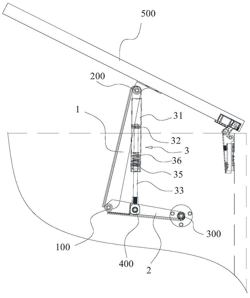
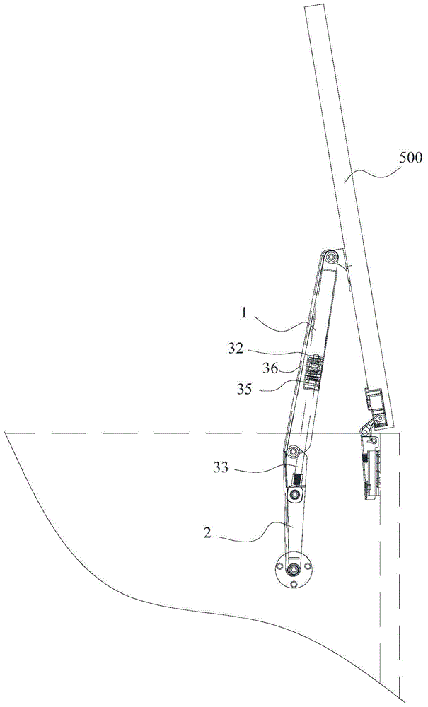
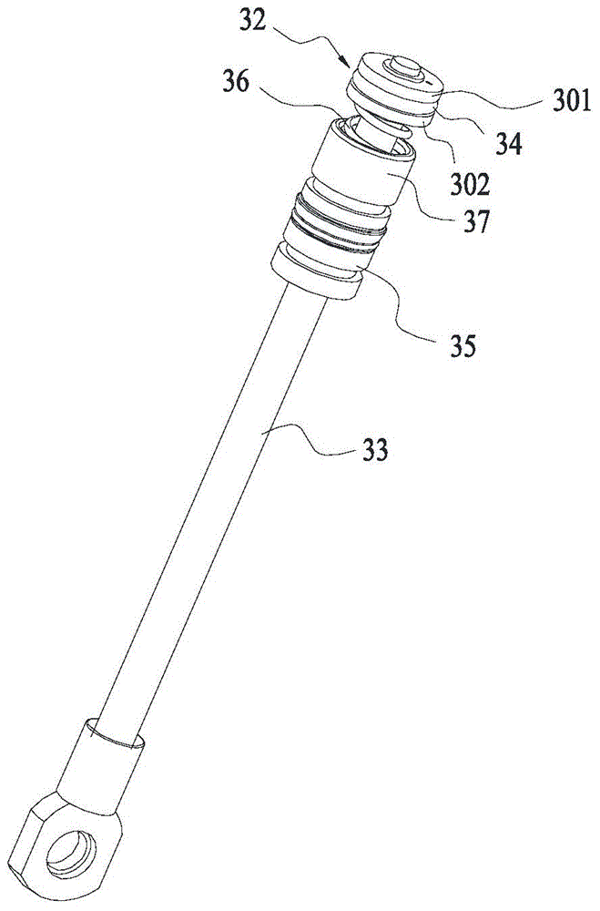
[0027] Below, in conjunction with accompanying drawing and specific embodiment, the present invention is described further:

[0028] Such as Figure 1~4 The shown pneumatic turning device comprises a long arm 1, a short arm 2 and a cylinder 3, one end of the long arm 1 is hinged to one end of the short arm 2 to form a first hinge point 100, and the other end of the long arm 1 is set as the first hinge end 200, the other end of the short arm 2 is set as the second hinged end 300, and the cylinder 3 includes a cylinder liner 31, a piston 32, a piston rod 33, a sealing ring 34, a guide sleeve 35, a spring 36, lubricating oil (not shown in the figure) ) and nitrogen (not shown in the figure), the guide sleeve 35 is airtightly inserted into the sleeve port of the cylinder liner 31, the lubricating oil and nitrogen are built into the cylinder liner 31, and the end of the cylinder liner 31 opposite to the sleeve port is hinged to the first The end 200 is hinged, the piston rod 33 is...


PUM


Abstract

The invention discloses a pneumatic turnover device. The pneumatic turnover device comprises a long arm, a short arm and an air cylinder; the air cylinder comprises an air cylinder sleeve, a piston, a piston rod, a sealing ring, a guide sleeve, a spring, lubricating oil and nitrogen, the guide sleeve is inserted into a sleeve opening of the air cylinder sleeve in an airtight mode, the lubricating oil and the nitrogen are contained in the air cylinder sleeve, the end, opposite to the end with the sleeve opening, of the air cylinder sleeve is hinged to the first hinge end, and the piston rod is connected to the guide sleeve in an airtight penetrating mode; the piston is fixed to one end of the piston rod and is located in the air cylinder sleeve, one end of the spring is fixedly connected to the inner side end of the guide sleeve, the other end of the spring extends to the interior of the air cylinder sleeve in the axial direction of the piston rod, an annular groove is formed in the peripheral wall of the piston, the piston is divided by the annular groove so as to form a first annual plug far away from the guide sleeve and a second annual plug close to the guide sleeve, and the first annular plug is in clearance fit with the air cylinder sleeve. By means of the pneumatic turnover device, after the piston rod is stressed, the piston stably slides in the piston sleeve, a rotating plate is driven to be stably opened and closed and can be stopped at any position in the middle, and the pneumatic turnover device is convenient to use.

Description

technical field [0001] The invention relates to a pneumatic overturning device and a locker using the device. Background technique [0002] The existing pneumatic overturning device used on the locker is a device for turning over the table top and switching the table top between closed and open states. The overturning device generally uses an ordinary cylinder, or a snap-in hinge or a gas spring or a damper, etc. Due to the unbalanced force on the cylinder piston, it can only achieve unstable opening or closing of the table, and when opening or closing the table During the process, it cannot be stopped at any position, which brings certain inconvenience. The damper is easy to break, and it cannot stop in the middle, and the service life is short, and the use effect is poor. [0003] In addition, when the table top is flipped to fast closing, because the air pressure in the cylinder increases exponentially, and the gravity provided by the table itself will be mostly transfer...

Claims


Application Information

Patent Timeline
IPC IPC(8): A47B49/00
Inventor 陈胜镛曹永乐
Owner 佛山市永桦锠胜家居用品有限公司
Why Eureka
Try Eureka