Forging and forming process of complex I-shaped connector
A forming process and I-shaped technology, which is applied in the field of mechanical processing, can solve problems such as the forging and forming process of complex I-shaped connectors, and achieve the effects of reducing workpiece defects, improving the mechanical properties of the workpiece, and stabilizing the forming process
- Summary
- Abstract
- Description
- Claims
- Application Information
AI Technical Summary
Problems solved by technology
Method used
Image
Examples
Embodiment 1
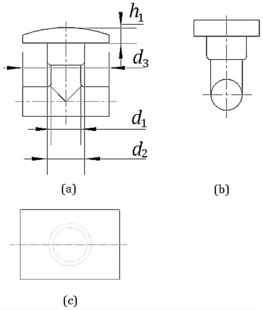
[0032] Such as figure 1 As shown, this embodiment includes the following steps:
[0033] The first step, blanking, adopts 20# steel annealed bar stock, in which: the height of the bar stock is 40mm, the diameter is 3.6mm, and the diameter of the stock is smaller than the diameter of the middle rod of the connecting head by d 1 The diameter is 0.2mm smaller.
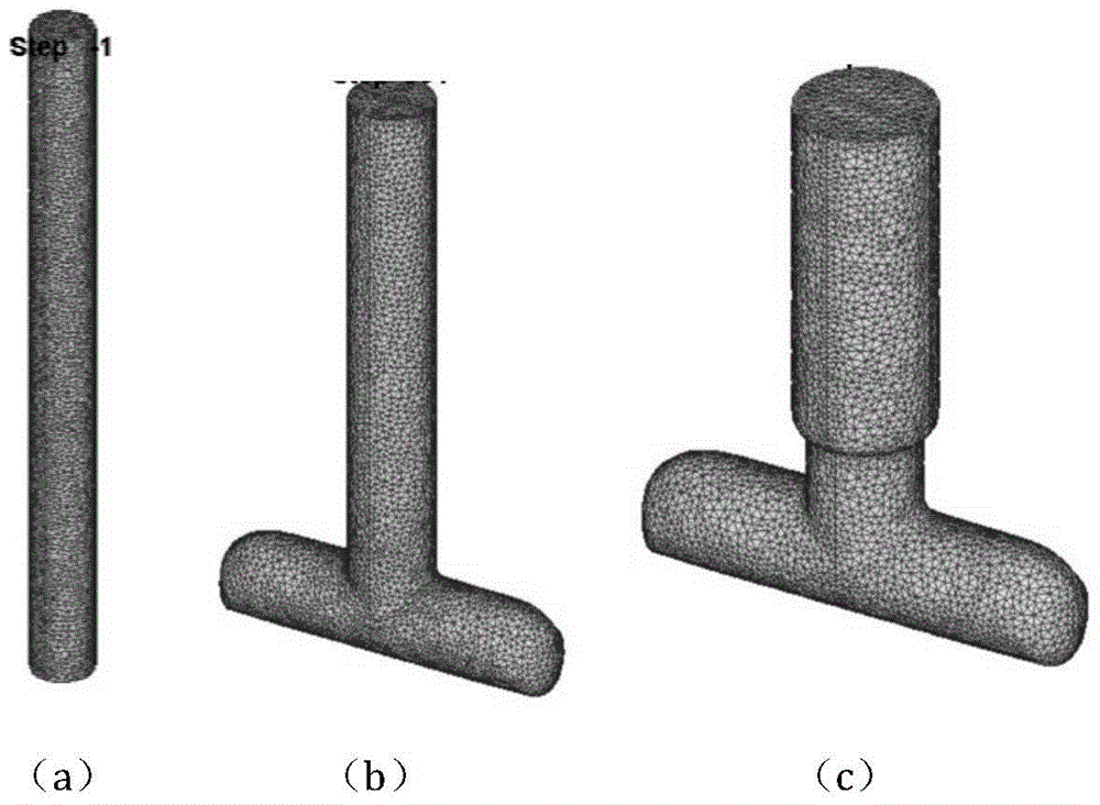
[0034] The second step is to extrude the cylindrical blank for the preparation of the connector, and the diameter of the die cavity is D 1 The upper die, the lower die and the sleeve are pressed together by 14.9 mm to obtain the shape of the upper end head, so that the upper end of the workpiece is completely filled with the length d 4 greater than d 3 = 11.8 mm.
[0035] Phosphorus saponification is used for lubrication in the extrusion process.
[0036] The extrusion die used in the extrusion includes: a laterally separable die and a floating control guide sleeve, which can realize the forming of the head with a la...
Embodiment 2
[0052] This embodiment includes the following steps:
[0053] The first step, blanking, adopts 15# steel annealed bar stock, in which: the bar stock height is 40mm, the diameter is 3.6mm, and the diameter of the stock is smaller than the diameter of the middle rod of the connecting head by d 1 The diameter is 0.2mm smaller.
[0054] The second step is to extrude the cylindrical blank for the preparation of the connector, and the diameter of the die cavity is D 1 The upper die, the lower die and the sleeve are pressed together by 14.9 mm to obtain the shape of the upper end head, so that the upper end of the workpiece is completely filled with the length of d 4 greater than d 3 = 11.8 mm.
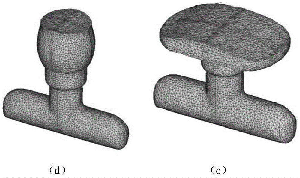
[0055] The third step is to upset the stem of the workpiece. The upper die, the lower die and the sleeve are pressed together by 7.85 mm to make the blank fill the entire die cavity. mm, the upper half of the stem forms a step.
[0056] The fourth step is to pre-forge the upper part of ...
Embodiment 3
[0059] This embodiment includes the following steps:
[0060] The first step, blanking, adopts 8# steel annealed bar stock, in which: the height of the bar stock is 40mm, the diameter is 3.6mm, and the diameter of the stock is smaller than the diameter of the middle rod of the connecting head by d 1 The diameter is 0.2mm smaller.
[0061] The second step is to extrude the cylindrical blank for the preparation of the connector, and the diameter of the die cavity is D 1 The upper die, the lower die and the sleeve are pressed together by 14.9 mm to obtain the shape of the upper end head, so that the upper end of the workpiece is completely filled with the length of d 4 greater than d 3 = 11.8 mm.
[0062] The third step is to upset the stem of the workpiece. The upper die, the lower die and the sleeve are pressed together by 7.85 mm to make the blank fill the entire die cavity. mm, the upper half of the stem forms a step.
[0063] The fourth step is to pre-forge the upper pa...
PUM
 Abstract
Description
Claims
Application Information
 - R&D
- Intellectual Property
- Life Sciences
- Materials
- Tech Scout
- Unparalleled Data Quality
- Higher Quality Content
- 60% Fewer Hallucinations
Browse by: Latest US Patents, China's latest patents, Technical Efficacy Thesaurus, Application Domain, Technology Topic, Popular Technical Reports.
© 2025 PatSnap. All rights reserved.Legal|Privacy policy|Modern Slavery Act Transparency Statement|Sitemap|About US| Contact US: help@patsnap.com


