Rotatable workpiece clamping mechanism for automatic cutter grinding machine

A technology of tool grinder and clamping mechanism, which is applied in the direction of grinding workpiece brackets, manufacturing tools, and other manufacturing equipment/tools, etc. It can solve the problems of affecting tool accuracy, low clamping accuracy, and tool scrapping, and achieves improved clamping. Accuracy, the effect of improving accuracy

Inactive Publication Date: 2015-07-22
DJTOL GRINDING MACHINE GRP
View PDF0 Cites 6 Cited by
  • Summary
  • Abstract
  • Description
  • Claims
  • Application Information

AI Technical Summary

Problems solved by technology

[0002] In the field of mechanical processing, especially in the process of cutting or drilling, when the cutting or drilling tool is worn, it is necessary to sharpen the tool. Grinding on a rotating grinding wheel makes the knife have a sharp edge. This is a sharpening method that depends on the personal skills of the operator. The quality of the sharpening is unstable, and the efficiency of this sharpening method is relatively low. Now there are many fields that use CNC The biggest feature of CNC tool grinding is high grinding efficiency. However, the clamping of the tool in the existing CNC tool grinder is a one-time fixed clamping, that is, the tool that needs to be ground is directly clamped. Fix it on the clamping head of the tool, and then perform the tool setting on the clamped tool that needs to be ground. Since the one-time fixed clamping is only one point when you set the tool, it cannot be rotated. Generally, the clamping accuracy is not high, and sometimes there will be deviations in the clamping, so this will seriously affect the accuracy of tool grinding, and in severe cases, the tool may be scrapped.

Method used


Image

  • Rotatable workpiece clamping mechanism for automatic cutter grinding machine
  • Rotatable workpiece clamping mechanism for automatic cutter grinding machine
  • Rotatable workpiece clamping mechanism for automatic cutter grinding machine

Examples


Embodiment Construction

[0018] The following descriptions are only preferred embodiments embodying the principles of the present invention, and do not therefore limit the protection scope of the present invention

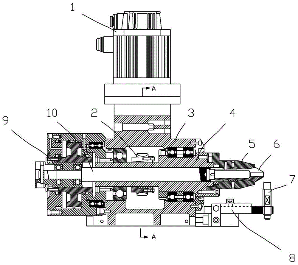
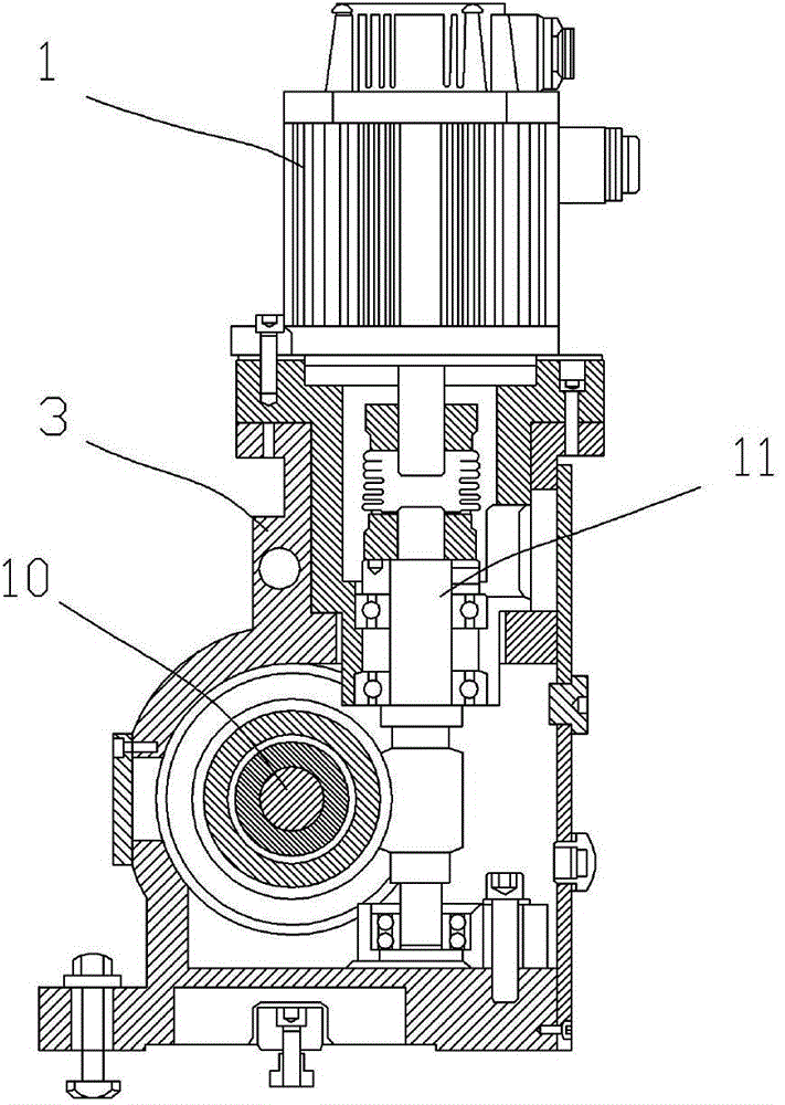
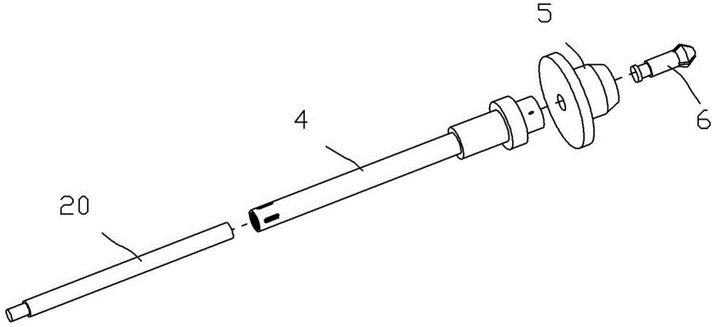
[0019] Such as Figures 1 to 4 Shown is an embodiment of a rotatable workpiece clamping mechanism used on an automatic tool grinding machine of the present invention, which includes a base body 3 and a motor 1, the motor 1 is installed on the base body 3, and the base body 3 There is a mounting through hole on the top, and the rotating shaft 4 is pivotally installed in the mounting through hole. The front end of the rotating shaft 4 is fixed with a mounting plate 5. The rotating shaft 4 and the mounting plate 5 have a connected inner hole. The central pull rod 10 It is movably installed in the inner hole of the rotating shaft 4, the front end of the center tie rod 10 is connected with the clamping head 6, the rear end of the center tie rod 10 is connected with the piston 14 of the cylinder...


PUM

PropertyMeasurementUnit
lengthaaaaaaaaaa
widthaaaaaaaaaa
heightaaaaaaaaaa

Abstract

The invention discloses a rotatable workpiece clamping mechanism for an automatic cutter grinding machine. The mechanism comprises a base body and a motor, wherein the motor is mounted on the base body; the base body has a mounting through hole; a rotating shaft is pivoted and mounted in a mounting through hole; a mounting disc is fixed at the front end of the rotating shaft; the rotating shaft and the mounting disc have communicated inner holes; a center pull rod is movably mounted in the inner hole of the rotating shaft; the front end of the center pull rod is connected with a clamping head part; the back end of the center pull rod is connected with a piston of the cylinder; the clamping head part is movably mounted in the inner hole of the mounting disc; the inner wall of the rotating shaft has an inclined surface; the outer wall of the clamping head part has an inclined taper surface fitting an inclined surface; a center hole for placing a workpiece is formed in the clamping head part; and the rotating shaft is driven by the motor. The mechanism can improve the claming precision of a cutter required to be sharpened, and further can the cutter sharpening precision.

Description

Technical field: [0001] The invention relates to the technical field of tool grinding machines, in particular to a rotatable workpiece clamping mechanism for automatic tool grinding machines. Background technique: [0002] In the field of mechanical processing, especially in the process of cutting or drilling, when the cutting or drilling tool is worn, it is necessary to sharpen the tool. Grinding on a rotating grinding wheel makes the knife have a sharp edge. This is a sharpening method that depends on the personal skills of the operator. The quality of the sharpening is unstable, and the efficiency of this sharpening method is relatively low. Now there are many fields that use CNC The biggest feature of CNC tool grinding is high grinding efficiency. However, the clamping of the tool in the existing CNC tool grinder is a one-time fixed clamping, that is, the tool that needs to be ground is directly clamped. Fix it on the clamping head of the tool, and then perform the tool...

Claims


Application Information

Patent Timeline
Patent Type & Authority Applications(China)
IPC IPC(8): B24B3/00
CPCB24B3/00B24B41/06
Inventor 胡永龙
Owner DJTOL GRINDING MACHINE GRP
Why Eureka
Try Eureka