Landing gear of rotor unmanned aerial vehicle (UAV)

A technology of unmanned aerial vehicles and landing gear, which is applied in the direction of landing gear, aircraft parts, chassis, etc. It can solve the problems of personal safety, damage to propellers, etc., and achieve the effect of avoiding unsafe factors and avoiding damage

Active Publication Date: 2015-07-22
厦门腾希航空科技有限公司
View PDF7 Cites 32 Cited by
  • Summary
  • Abstract
  • Description
  • Claims
  • Application Information

AI Technical Summary

Problems solved by technology

This kind of landing gear has good adaptability on flat ground, but it will be greatly restricted in the field wi

Method used


Image

  • Landing gear of rotor unmanned aerial vehicle (UAV)
  • Landing gear of rotor unmanned aerial vehicle (UAV)
  • Landing gear of rotor unmanned aerial vehicle (UAV)

Examples


Embodiment Construction

[0023] The following embodiments will describe the present invention in detail with reference to the accompanying drawings.

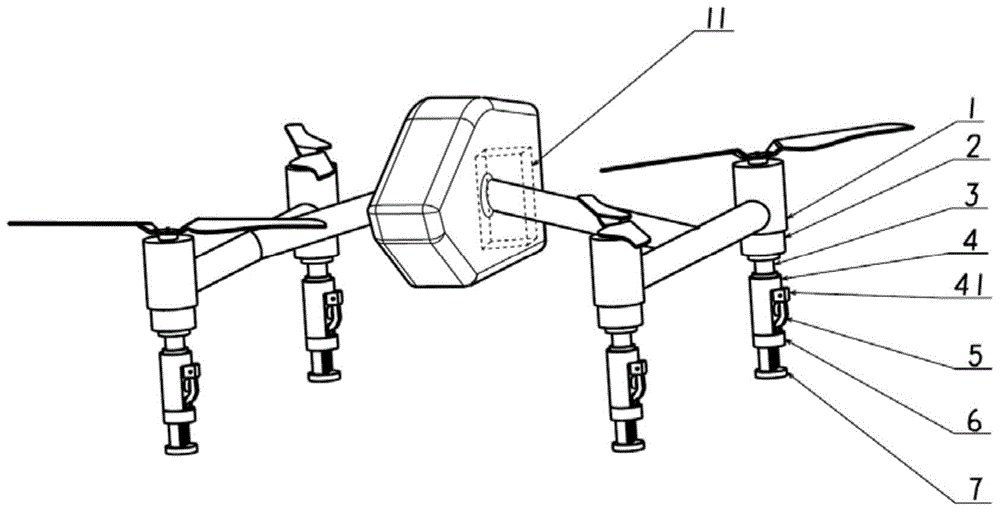
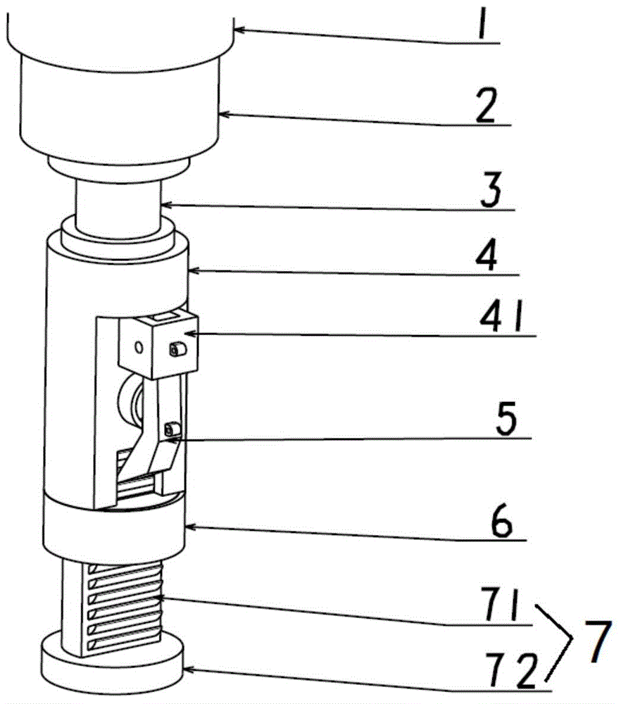
[0024] see Figure 1~5 , the four rotor UAVs are respectively installed under the four steering gear housings 1 of the quadrotor UAV. Each rotor drone landing gear includes a buffer cylinder 3, a ratchet mechanism and a pawl control circuit.

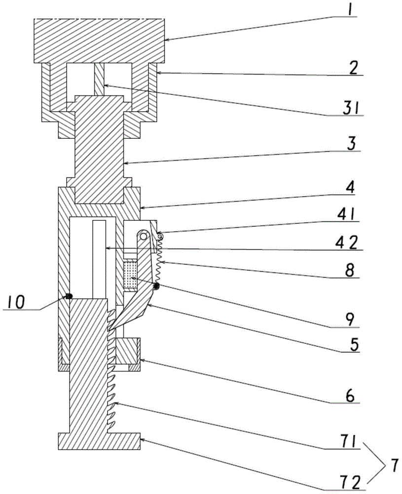
[0025] The upper end of the outer cover 3 of the buffer cylinder 3 is externally connected to the outer cover of the steering gear of the unmanned aerial vehicle, and the lower end of the outer cover 3 of the buffer cylinder 3 is connected with the sleeve of the ratchet mechanism. 5. Pawl return spring 8, pawl support 41 on sleeve 4, ratchet bar slide rail 42 inside sleeve 4, contact switch 10 inside sleeve 4, sleeve cover 6 and sleeve 4 The lower end is screwed, the ratchet bar 7 extends into the sleeve 4 and slides with the ratchet bar slide rail 42, the lower end of the ratchet bar 7 is provided with a ratche...


PUM


Abstract

The invention discloses a landing gear of a rotor unmanned aerial vehicle (UAV). The landing gear comprises a buffer cylinder, a ratchet mechanism and a pawl control circuit, wherein the upper end of the shield of the buffer cylinder is externally connected with a UAV steering engine shield, the lower end of the shield of the buffer cylinder is connected with the sleeve of the ratchet mechanism; the ratchet mechanism is provided with the sleeve, a sleeve shield, a ratchet bar, a pawl and a pawl reset spring; a pawl support is arranged on the sleeve; a ratchet bar sliding rail is arranged in the sleeve; a contact switch is arranged in the sleeve; the sleeve shield is screwed with the lower end of the sleeve; the ratchet bar extends into the sleeve and is matched with the ratchet bar sliding rail in a sliding manner; a ratchet bar support is arranged at the lower end of the ratchet bar and is in contact with the ground; ribs are arranged at two sides of the ratchet bar; the upper end of the pawl is hinged with the pawl support; the lower end of the pawl is matched with the ratchet of the ratchet bar; one end of the pawl reset spring is connected with the pawl support and the other end is connected with the pawl; the pawl control circuit is provided with a battery, a contact switch and an electromagnet; the contact switch is arranged in the inner wall of the sleeve and the electromagnet is arranged between the sleeve and the pawl of the ratchet mechanism.

Description

technical field [0001] The invention relates to a rotary-wing unmanned aerial vehicle, in particular to a landing gear of a rotary-wing unmanned aerial vehicle capable of adapting to terrain. Background technique [0002] In recent years, drone technology has developed by leaps and bounds. Due to its low cost, good maneuverability, strong survivability, and no risk of casualties, UAVs occupy an extremely important position in modern military warfare and have a very broad prospect in the civilian field. The current UAVs mainly include fixed-wing UAVs and rotary-wing UAVs. Compared with fixed-wing drones, rotary-wing drones have the advantages of simple structure, flexible control, vertical take-off and landing, hovering or inverted flight, etc., and are widely used in aerial photography and police applications. [0003] At present, the landing gear of the rotor UAV is basically fixed, and the landing gear of a small number of rotor UAVs can be moved up and down synchronousl...

Claims


Application Information

Patent Timeline
IPC IPC(8): B64C25/10B64C25/58
Inventor 欧阳智贤滕健徐名赫郑云隆尤延铖
Owner 厦门腾希航空科技有限公司
Why Eureka
Try Eureka