
a traction machine

A machine base and rotor technology, applied in the field of traction machines, can solve problems such as the increase of traction machine parts, elevator vibration and noise, and inertia increase, and achieve the effects of saving manual installation, improving safety and avoiding failure

Active Publication Date: 2017-09-22
SUZHOU DEAO ELEVATOR
View PDF14 Cites 1 Cited by
  • Summary
  • Abstract
  • Description
  • Claims
  • Application Information

AI Technical Summary

Problems solved by technology

The disadvantages of this invention are: 1) because the brake wheel of the traction machine is located on the same side as the traction wheel and is arranged adjacently, the brake surface is very easily affected by the grease of the steel wire rope like this, thereby causing the friction coefficient of the brake surface to decrease , the normal operation of the elevator has a catastrophic impact; 2) Since the brake is set outside the traction machine, the noise of the brake is directly transmitted outside, resulting in an increase in the noise of the traction machine. The application in the elevator will directly affect the running quality of the elevator; 3) In order to reduce the noise, the gap between the friction plate and the brake wheel is usually set very small, so that when the brake arm acts on the brake wheel, due to The action time of the two brakes cannot be consistent, so it may cause the brake wheel to deform in the direction of the force, which may cause the other brake arm to contact the brake wheel, thus causing the friction plate of the other brake arm to wear. Reduce the service life of the brake arm, and may bring vibration and noise to the operation of the elevator; at the same time, in order to ensure that the brake wheel and the brake arm have sufficient rigidity, it is necessary to design a sufficiently strong brake arm and brake wheel, which will increase The cost of the traction machine, and because the inertia of the brake wheel increases, the torque requirement of the traction machine is increased, thereby further increasing the cost of the traction machine; 4) Since the brake arm and the electromagnet are arranged outside the traction machine, On the one hand, the outer dimension of the traction machine becomes larger, including the required axial dimension of the brake wheel and the height required by the electromagnet, which affects the appearance of the traction machine. It is basically impossible for the traction machine to be applied to machine room-less elevator products. , on the other hand, the parts of the traction machine increase, the processing amount of the parts increases, and the cost of the traction machine increases; 5) Since the magnetic steel is installed on the rotor, and the braking surface is also located on the rotor, the braking When the arm exerts a braking force on the brake wheel, it will have an impact on the magnet steel. Such impact will directly affect the connection between the magnet steel and the rotor, which may cause the magnet steel to fall off from the rotor, causing serious accidents and causing serious damage to the elevator. to seriously affect

Method used


Image

  • a traction machine
  • a traction machine
  • a traction machine

Examples


Embodiment 1

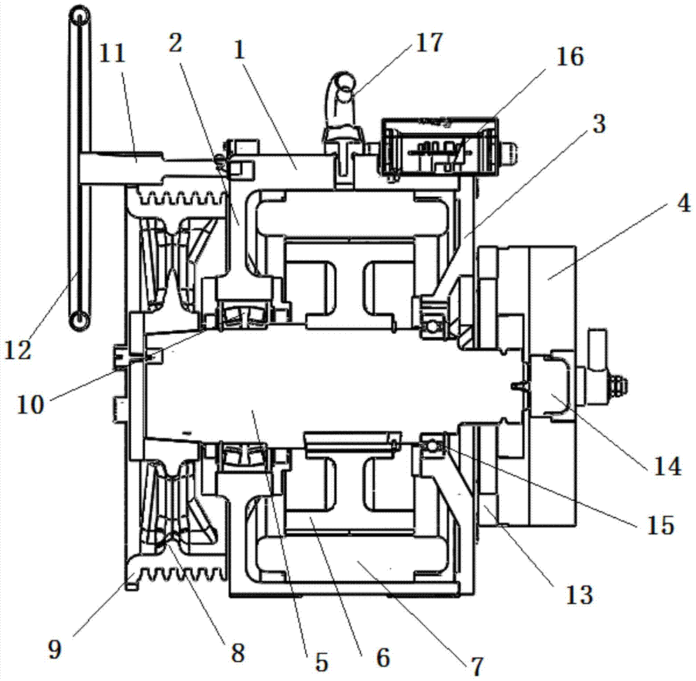
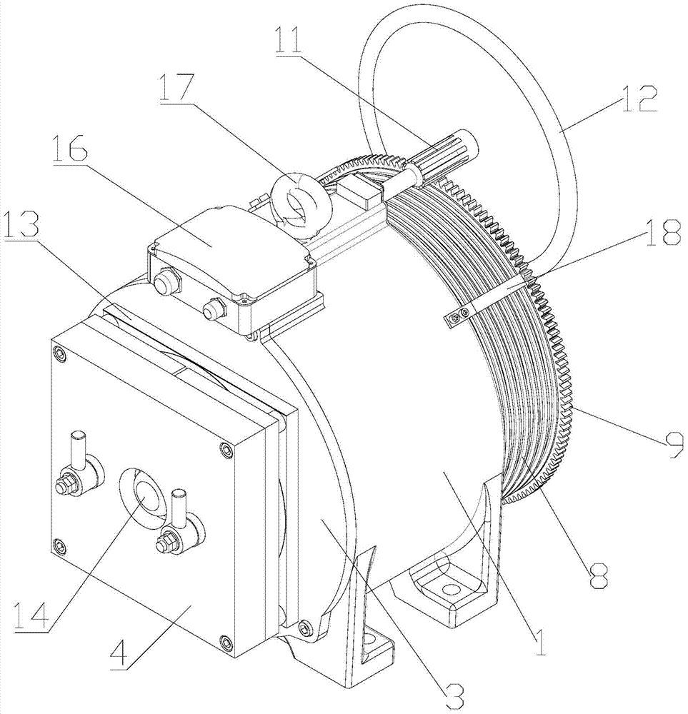
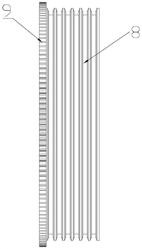
[0028] Such as figure 1 The traction machine described in the present invention is shown, such as figure 2 As shown, including machine base 1, one end of said machine base 1 is integrally formed with side cover 2, said machine base 1 and side cover 2 are preferably made of seamless steel, which can effectively ensure the overall structure of the traction machine stability, and is conducive to long-term use, the other end is fixedly installed with a brake disc end cover 3, and a stator 7 is fixedly installed in the base 1, and the stator 7 is preferably a stator core with windings, and the stator 7 is equipped with a rotatable rotor assembly;

[0029] The rotor assembly includes a shaft 5 and a rotor yoke 6, such as Figure 5 As shown, the rotating shaft 5 is statically connected to the inner wall of the rotor yoke 6 through a flat key 21, and a plurality of arc-shaped magnets 19 are uniformly glued on the outer wall of the rotor yoke 6, and the arc-shaped magnets 19 is als...


PUM


Abstract

The invention relates to a traction machine. A side cover is integrally formed in one end of a machine base, and a brake disc end cover is fixedly installed at the other end of the machine base. A stator is fixedly installed inside the machine base, and a rotary rotor assembly is installed inside the stator. The rotor assembly comprises a rotation shaft and a rotor magnet yoke, the rotation shaft is in static connection with the inner wall of the rotor magnet yoke through a flat key, a plurality of arc magnetic steel pieces are evenly glued to the outer wall of the rotor magnet yoke, and the arc magnetic steel pieces are fixed to the outer wall of the rotor magnet yoke through taper bolts. The part, located at the outer side of the side cover, of the rotation shaft is connected with a traction gear. The traction gear comprises a traction wheel and a gear which are integrally formed. The side, where the brake disc end cover is located, of the rotation shaft is connected with a brake, and a brake installation plate is fixed between the brake and the brake disc end cover. The arc magnetic steel pieces are fixed in two modes. The traction machine is safe and reliable, is stable in overall operation, effectively insulates the temperature through the brake installation plate, reduces the temperature of the brake, and avoids property loss and casualties caused by failures of the brake.

Description

technical field [0001] The invention relates to a traction machine, in particular to a traction machine used for an elevator. Background technique [0002] The elevator traction machine is the power equipment of the elevator, also known as the elevator host. The function is to convey and transmit power to make the elevator run. It is composed of motor, brake, coupling, reduction box, traction wheel, frame, guide wheel and auxiliary turning hand wheel. [0003] Existing traction machine, such as the disclosed elevator traction machine of Chinese invention patent (notification number CN1141775C). The electromagnet and the brake arm of the traction machine are arranged outside the traction machine, and the brake arm acts on the brake wheel of the outer rotor of the traction machine to generate a braking force, thereby braking the traction machine. The disadvantages of this invention are: 1) because the brake wheel of the traction machine is located on the same side as the tr...

Claims


Application Information

Patent Timeline
Patent Type & Authority Patents(China)
IPC IPC(8): B66B11/04H02K7/102H02K7/116
CPCB66B11/04H02K7/102H02K7/116
Inventor 沈华葛晓东
Owner SUZHOU DEAO ELEVATOR
Learn More