
A super-high integral steel-plastic grid reinforced earth abutment retaining wall structure and its construction method

A steel-plastic grille and construction method technology, which is applied in infrastructure engineering, underwater structures, bridges, etc., can solve the problems of multiple raw materials, manpower, time, large area of ​​reinforced soil, and increased construction costs. , to achieve the effect of shortening the construction period, convenient construction and large friction coefficient

Active Publication Date: 2017-02-01
NO 1 CONSTR ENG CO LTD OF GUIZHOU CONSTR & ENG GRP
View PDF1 Cites 0 Cited by
  • Summary
  • Abstract
  • Description
  • Claims
  • Application Information

AI Technical Summary

Problems solved by technology

This scheme adopts a composite structure, that is, anti-slide piles are installed at the bottom of the front end of the reinforced soil structure. Although it can strengthen its strength to prevent the wall from sliding and improve the strength of the entire reinforced soil wall, it requires more raw materials, manpower and time. , leading to an increase in project construction costs and an increase in the construction period; in addition, the addition of anti-slide piles requires more floor area than the traditional reinforced earth wall structure, making the entire reinforced earth force occupy a larger area after completion

Method used


Image

  • A super-high integral steel-plastic grid reinforced earth abutment retaining wall structure and its construction method
  • A super-high integral steel-plastic grid reinforced earth abutment retaining wall structure and its construction method
  • A super-high integral steel-plastic grid reinforced earth abutment retaining wall structure and its construction method

Examples


Embodiment

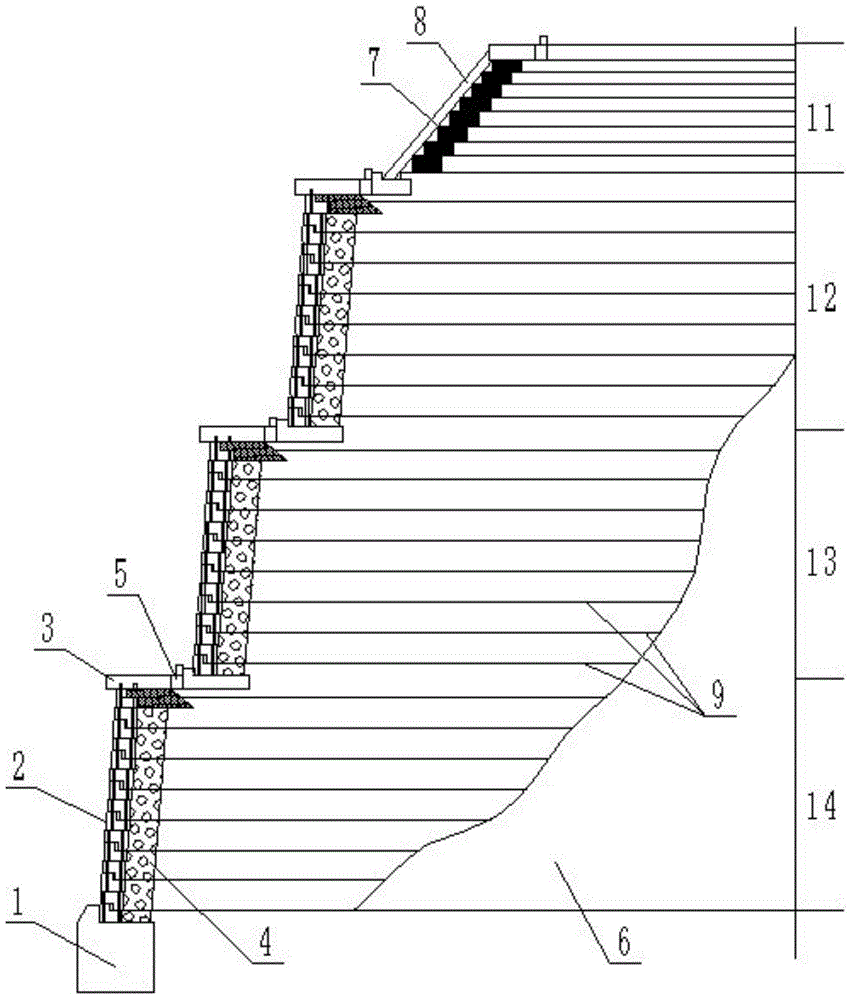
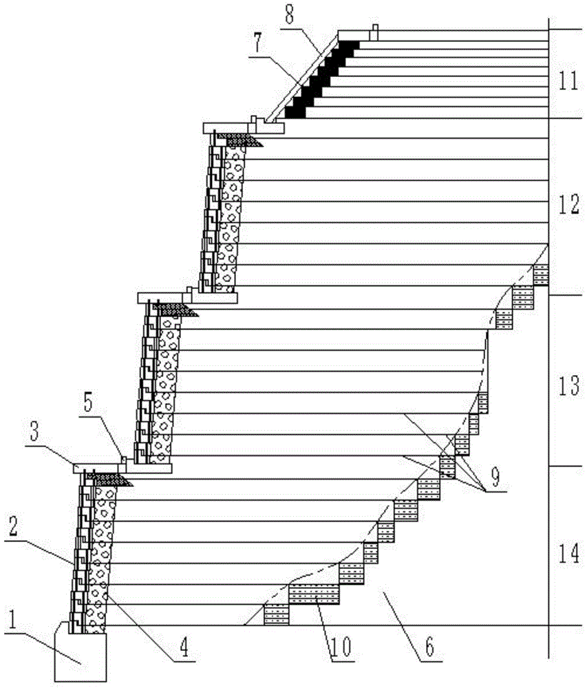
[0061] Embodiment: The K4+615 bridge project of the west section of Pingba, Gui'an Avenue, Guizhou adopted the super-high integral steel-plastic grid reinforced soil abutment construction technology provided by the present invention, and the overall super-high reinforced soil abutment wall in the project The height reaches 32m. The specific construction is as follows:

[0062] Construction preparation: According to the model and specification of the overall steel-plastic grille on the drawing, the overall steel-plastic grille will be inspected according to the regulations after entering the site, and the breaking strength, elongation, single strip width, and single strip thickness will be randomly inspected for each batch. Hole size, joint stripping force and deflection rate; foundation trench excavation and compaction: excavate several foundation trenches arranged at the same height along the mountain 6 from top to bottom; prefabricated panel 2: panel 2 is prefabricated with ...


PUM


Abstract

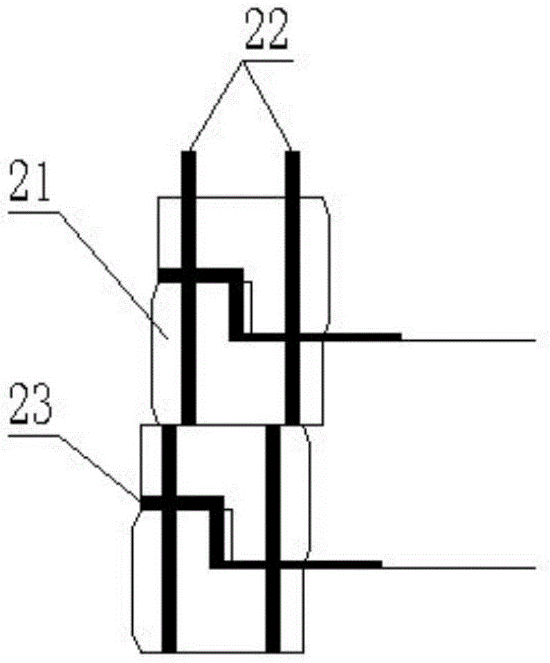
The invention discloses an ultrahigh integrated plastic-steel grid reinforced soil abutment retaining wall structure and a construction method thereof. The structure comprises a first-level abutment, a second-level abutment, a third-level abutment and a fourth-level abutment which are distributed in a stepped mode from top to bottom along a mountain. The first-level abutment comprises a plurality of layers of integrated plastic-steel grids, a first-level bagged aggregate layer is arranged on the outside of the integrated plastic-steel grid away from the mountain, and a reinforced concrete panel is arranged on the outside of the first-level bagged aggregate layer. The second-level abutment, the third-level abutment and the fourth-level abutment each comprises a plurality of evenly distributed integrated plastic-steel grids, an aggregate reversed filter is arranged at the front ends of the integrated plastic-steel grids, a panel is arranged outside the aggregate reversed filter, a cap beam is arranged at the bottom of the panel and the bottom of the aggregate reversed filter, the cap beam is provided with a platform, and a catchwater is arranged on the platform. Compared with a traditional reinforced soil structure, the ultrahigh integrated plastic-steel grid reinforced soil abutment retaining wall structure has the advantages of being short in work time, convenient and quick to construct, high in strength, high in bearing capacity, large in friction coefficient, high in shock resistance, small in occupied space and the like.

Description

technical field [0001] The invention relates to the technical field of building construction, in particular to a structure and a construction method of a reinforced soil abutment, in particular to an ultra-high integral steel-plastic grid reinforced soil abutment retaining wall structure and a construction method thereof. Background technique [0002] The steel-plastic grid reinforced soil abutment construction technology is a new type of support and retaining structure. The reinforced soil abutment can effectively improve the interlocking and occlusion of the reinforced bearing surface by adding an integral steel-plastic grid to the soil of the filler. The effect is to greatly enhance the bearing capacity of the foundation, effectively restrain the lateral displacement of the soil, and enhance the stability of the foundation. However, the current reinforced earth abutment or retaining wall structure has a limited application range, and can only be constructed for mountains ...

Claims


Application Information

Patent Timeline
Patent Type & Authority Patents(China)
IPC IPC(8): E02D29/02E01D19/02E01D21/00
Inventor 张义勇傅亚松付定鑫刘承华余万江罗昕谢光亚毛华祥查长权刘璇崔冲贺贵元程继方张钊吴松王永
Owner NO 1 CONSTR ENG CO LTD OF GUIZHOU CONSTR & ENG GRP
Learn More