
High-energy-consumption large-deformation buffer device

A cushioning device and large deformation technology, which is applied to building components, earthquake resistance, etc., can solve the problems of limitations and high complexity of damping devices

Inactive Publication Date: 2015-07-22
INST OF MOUNTAIN HAZARDS & ENVIRONMENT CHINESE ACADEMY OF SCI
View PDF8 Cites 0 Cited by
  • Summary
  • Abstract
  • Description
  • Claims
  • Application Information

AI Technical Summary

Problems solved by technology

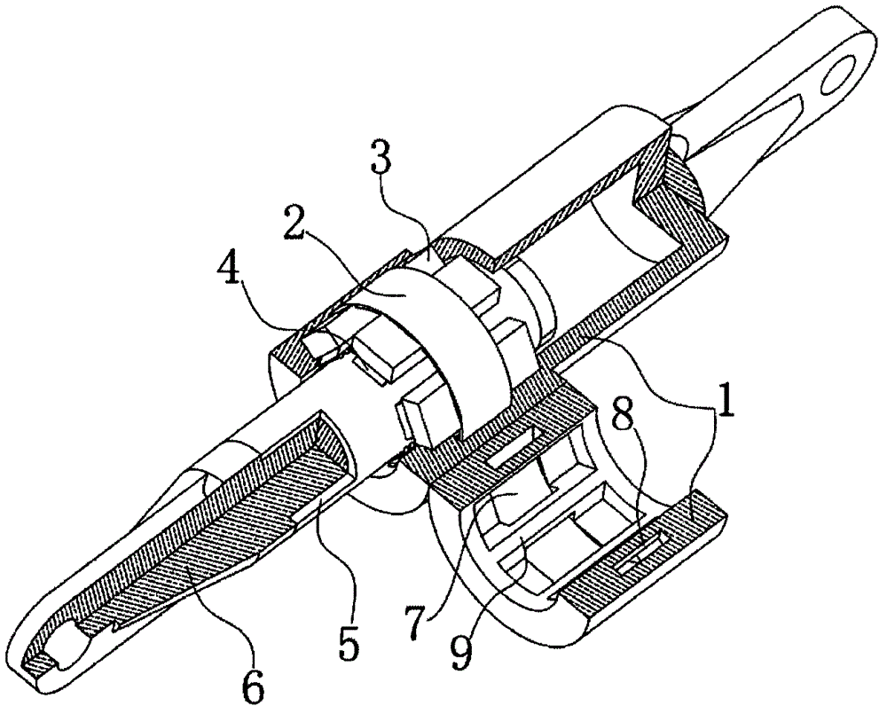
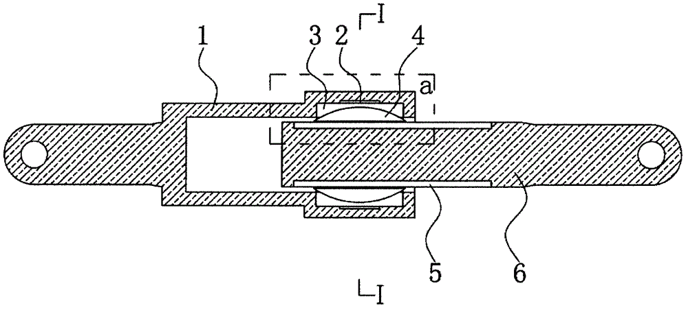
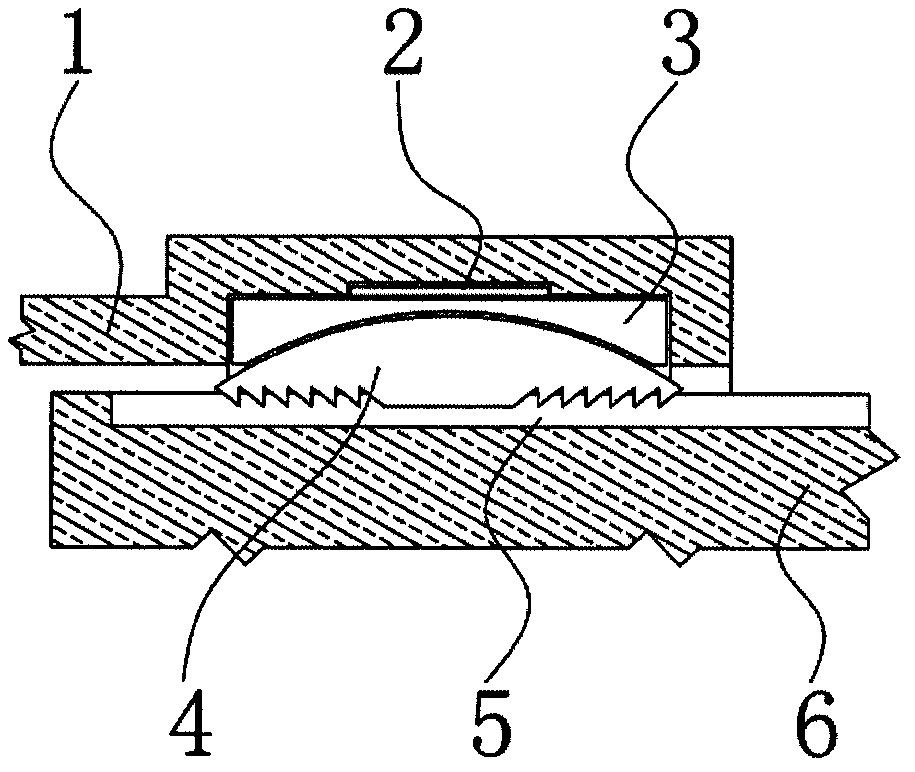
[0005] Aiming at the limitation of the performance of the existing damping device and the defects of high complexity, the present invention provides a high-energy-consuming and large-deformation buffer device that utilizes metal plastic deformation to generate damping force. The main components include: a shell 1, a shape memory alloy Ring 2, chute 3, shuttle-shaped claw 4, wear layer 5 and movable rod 6; there are hinged holes at both ends of the device for connecting with other structures, and the whole is in the shape of a rod column; It is surrounded by an alloy belt; there are partitions corresponding to the number of chutes inside the shell to evenly space the chute and the shuttle claw, and each partition has a gap, and the shape memory alloy strip is as wide as the gap, and the gap has an effect on the shape memory. The alloy ring has a constraining and limiting effect, so that it can move radially inward and bear the force in the axial direction. The shape memory alloy strip passes through these gaps against the surface A 7 and makes a circle. The shape memory alloy ring and There is a reserved space between surfaces B and 8, and the thickness of the reserved space matches the sum of the thickness of the loss layer plus the maximum shrinkage distance of the shape memory alloy ring; outside the partition, place the shape memory alloy ring, slide Groove, shuttle claw, wear layer and movable rod; the inner surface of the chute is an arc-shaped concave surface, and there is a groove on the outer surface of the chute that matches the inner surface of the shape memory alloy ring, and the axial direction of the arc surface on the bottom surface of the groove Orthogonal to the axial direction of the arc-shaped concave surface on the inner surface of the chute, the shape memory alloy ring adheres to the surface A, covers the groove on the outer surface of the chute, and hoops the chute; the shuttle claw 4 is shuttle-shaped, and the outer surface It is arc-shaped, which coincides with the curvature of the inner surface of the chute 3, so that the chute has a radially inward extrusion force and a thrust in the opposite direction of motion on the shuttle-shaped claw through the circular-arc-shaped sliding surface, and the shuttle-shaped claw has another One surface has tooth-shaped protrusions, and the direction of the tooth-shaped protrusions at both ends is towards the center. The pressing force of the tooth-shaped protrusions on the loss layer 5 can make the starting force of the device reach the required value of engineering design; The corresponding reserved position is tightly attached; there is a gap between the movable rod, the sacrificial layer and the surface C of the casing, which allows the movable rod to slide freely in the axial direction of the casing with the sacrificial layer

Method used


Image

  • High-energy-consumption large-deformation buffer device
  • High-energy-consumption large-deformation buffer device
  • High-energy-consumption large-deformation buffer device

Examples


Embodiment Construction

[0040] Embodiments of the present invention will be described in detail below in conjunction with the accompanying drawings.

[0041] A high-energy-consuming large-deformation buffer device, its three-dimensional cut-away diagram is shown in figure 1 , Image 6 As shown, the main components include: shell 1, shape memory alloy ring 2, chute 3, shuttle claw 4, loss layer 5, movable rod 6; there are hinged holes at both ends of the device for connecting with other structures, and the overall shape is rod columnar; as Figure 2-Figure 5 As shown, the shape memory alloy ring is surrounded by a shape memory alloy strip with a rectangular cross section. There are 6 chutes and 6 shuttle claws respectively. There are 6 partitions with gaps inside the shell to evenly space the chute and shuttle claws. , the chute and the shuttle-shaped claws are distributed in a circular radial array on the cross-section of the device; the shape memory alloy strips are as wide as the gaps, and pass t...


PUM


Abstract

The invention relates to a high-energy-consumption large-deformation buffer device, and belongs to the field of disaster prevention and mitigation engineering. The high-energy-consumption large-deformation buffer device mainly comprises a shell (1), a shape memory alloy ring (2), sliding grooves (3), fusiform claws (4), a loss layer (5) and a movable rod (6). The whole high-energy-consumption large-deformation buffer device is in a rod column shape. The shell is internally provided with partitions with gaps, wherein the partitions correspond to the sliding grooves in number and evenly separate the sliding grooves from the fusiform claws. The shape memory alloy ring, the sliding grooves, the fusiform claws, the loss layer and the movable rod are sequentially placed outside the partitions from exterior to interior. The high-energy-consumption large-deformation buffer device has the advantages of being high in damping force, large in deformation range, low in hysteresis performance and the like and can be widely applied to the field of disaster prevention and mitigation engineering.

Description

technical field [0001] The invention relates to a civil engineering device, in particular to a high-energy-consuming and large-deformation buffer device, which is used for shock absorption and impact prevention of structures, and belongs to the field of disaster prevention and mitigation engineering. Background technique [0002] When the engineering structure is subjected to earthquake load or impact load, in order to prevent the damage of the structure from causing loss of people's lives and property, certain protective measures must be taken. In general engineering methods, in addition to measures to enhance the strength of the structure itself and optimize the structural design, the use of buffer and shock absorption measures can better reduce the damage to the engineering structure. At present, in civil engineering and disaster prevention engineering, there are many methods and measures to isolate and buffer structures, such as the foundation isolation device of buildin...

Claims


Application Information

Patent Timeline
Patent Type & Authority Applications(China)
IPC IPC(8): E04B1/98
Inventor 刘传正蒋先刚王洋江兴元
Owner INST OF MOUNTAIN HAZARDS & ENVIRONMENT CHINESE ACADEMY OF SCI
Learn More