Locking strip for vertical mounting

A technology of vertical installation and locking strips, applied in the direction of friction-clamped detachable fasteners, connecting components, mechanical equipment, etc. Long thread locking length, outstanding substantive features, and the effect of preventing dislocation and overturning

Active Publication Date: 2015-07-22
四川雷兹盾电子科技有限公司
View PDF7 Cites 1 Cited by
  • Summary
  • Abstract
  • Description
  • Claims
  • Application Information

AI Technical Summary

Problems solved by technology

However, this structure has been found to have many problems in practical applications. One is that the contact area is too small to clamp heavier plates, because the existing locking strips, locking grooves and plate contact surfaces are wedge-shaped slopes at both ends. Side, where the volume of the wedge is relatively small, and the corresponding contact side is also small; the second is that the wedge-shaped slope is used as the positioning surface between the existing wedge and the wedge. When the bolt is in a loose state, the wedge and the wedge The wedges are all easy to rotate relative to the bolts, which can easily cause the positioning surfaces between the wedges and the wedges to not match, and cannot be locked normally; the third is that there is no stable connection between the various parts of the existing locking strips Relationship, each component module is easy to fall when it is in a relaxed state. If the component falls on the PCB board during the disassembly and assembly of the actual application, it is easy to cause short-circuit damage to its components, which also limits the existing locking strip structure. Manual tools can be used, but it is difficult to use electric fast disassembly tools. Some people think of adding anti-drop nuts at the ends of long bolts to achieve electric operation, but this will increase the overall length of the locking bar and cause redundant components. It is cumbersome and inconvenient to use; the fourth is that when the locking strip is inserted in the vertical direction, since there is no mutual traction force between the wedges defined by the positioning surface, the action of gravity will make all the wedges move to their limit positions, which is not suitable for use requirements, and sometimes even get stuck to the edge of the chassis wall, which seriously affects the assembly efficiency

Method used


Image

  • Locking strip for vertical mounting
  • Locking strip for vertical mounting
  • Locking strip for vertical mounting

Examples


Embodiment

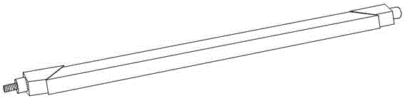
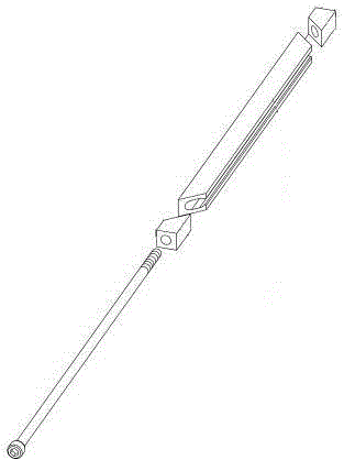
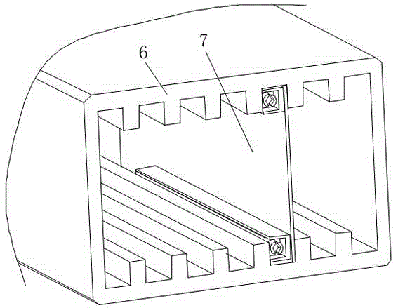
[0041] Such as image 3As shown, the locking strip for vertical installation is mainly used for the clamping installation of the chassis 6 and board 7 of military equipment, especially the clamping installation during vertical insertion, and is usually installed in the preset installation groove of the chassis. The locking bar is used to clamp the board to keep it stably in the chassis. When the board fails or needs maintenance, just adjust and loosen the locking bar to take off the board. Due to the design defect of the existing locking bar structure, if the power tool is used to disassemble, it is easy to cause the end wedge to fall, which will cause the short circuit of the board card circuit to fail, and when the locking bar is inserted and pulled in the vertical direction, it will be damaged due to gravity. The function makes the wedge part open at the maximum width, which seriously affects the insertion of the board and greatly increases the difficulty of board insertion...


PUM


Abstract

The invention discloses a locking strip for vertical mounting. The locking strip comprises a wedge-shaped fixing groove, a clamping wedge body, a wedge head screw rod, a rotating wedge block and a pulling reed which are connected with each other. The wedge-shaped fixing groove comprises an anti-turning groove body, a lower slope face, a lower skew surface and a lower clamping part. The clamping wedge body comprises a wedge body, an upper slope face, an upper skew surface and an upper clamping part. The wedge head screw rod comprises a screw rod main rod, a wedge head and a double-section thread section. The rotating wedge block comprises a rotating body, a cone wedge face, a mounting hole and a double-section inner thread part. The pulling reed comprises a reed body, a sleeve hole, an upper hook body and a lower hook body. The clamping part is arranged between the wedge-shaped fixing groove and the clamping wedge body. The pulling reed is subjected to sleeving connecting to achieve mutual traction balance between components. When the locking strip is inserted vertically, plate card inserting is not affected. The double-section inner thread part and the double-section thread section are ingeniously used for forming a thread anti-falling structure. An electric tool can carry out quick assembling and disassembling. Working efficiency is improved.

Description

technical field [0001] The invention relates to a locking strip, in particular to a locking strip for vertical installation. Background technique [0002] With the development of science and technology, the design of military equipment is increasingly inclined to miniaturization, integration and modularization. The first problem to be solved by military equipment is the vibration problem. How to ensure that the connection between the module and the motherboard does not fail under the condition of high-speed impact has always been the direction of connector efforts. The emergence of the locking strip as a structural part to improve the seismic strength of the board greatly reduces the difficulty of connector development. Therefore, there are more and more application environments for locking strips, from tanks and armored vehicles to various ships, to civil and military aircraft, to aerospace equipment. [0003] A high degree of integration also requires that the current e...

Claims


Application Information

Patent Timeline
IPC IPC(8): F16B2/14
CPCF16B2/14
Inventor 鄢登俊
Owner 四川雷兹盾电子科技有限公司
Why Eureka
Try Eureka