Damping fin applied to clutch driven disc, clutch driven disc and clutch

A damping plate and clutch technology, applied in the field of clutches, can solve the problems of large moment of inertia, high cost, limited vibration damping effect of the clutch driven plate, etc., and achieve the effects of reducing moment of inertia, improving vibration damping effect, and good NVH performance

Active Publication Date: 2015-07-22
SCHAEFFLER TECH AG & CO KG
View PDF8 Cites 17 Cited by
  • Summary
  • Abstract
  • Description
  • Claims
  • Application Information

AI Technical Summary

Problems solved by technology

[0007] The problem to be solved by the present invention is: the friction damping assembly in the existing clutch driven disc includes at least three parts, resulting in complex structure, high cost and large moment of inertia of the clutch driven disc
[0008] Another problem to be solved by the present invention is: the frictional damping torque value produced by t...

Method used


Image

  • Damping fin applied to clutch driven disc, clutch driven disc and clutch
  • Damping fin applied to clutch driven disc, clutch driven disc and clutch
  • Damping fin applied to clutch driven disc, clutch driven disc and clutch

Examples


Embodiment Construction

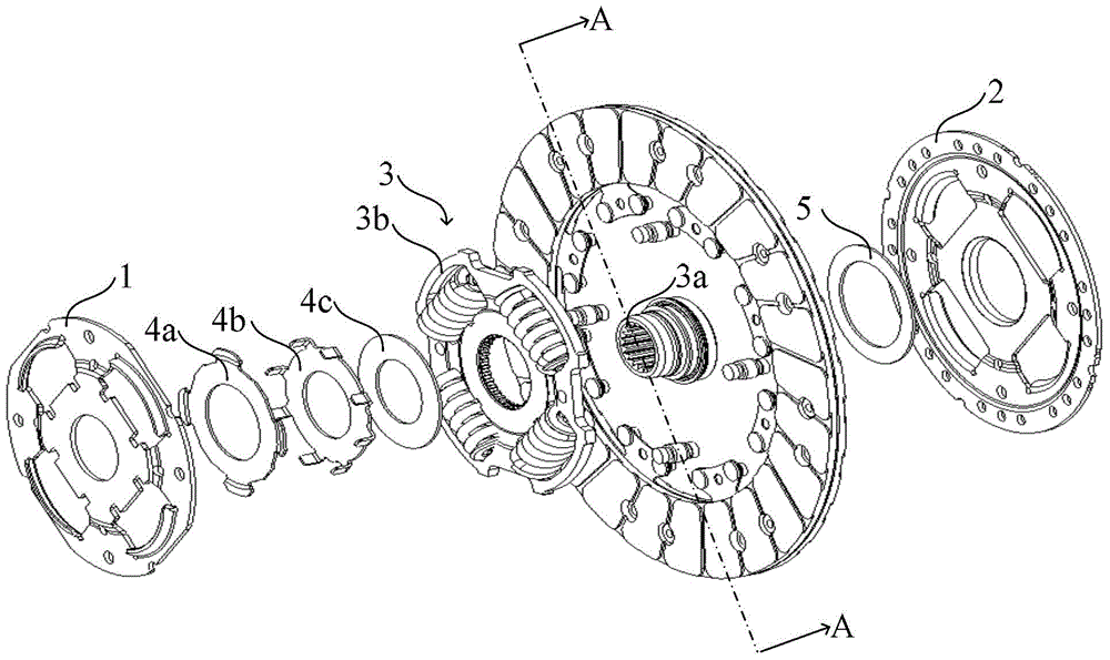
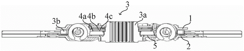
[0055] combine Figure 4 with Figure 5 As shown, the clutch driven disc of this embodiment includes:

[0056] Damping disc 10;

[0057] A driven disc body 20 fixedly connected to the damping disc 10 in a torsion-resistant manner;

[0058] A driven hub 30 rotatably located between the damping disc 10 and the driven disc body 20, the driven hub 30 has a hub core 31 and a flange 32 sleeved on the hub core 31;

[0059] A damping plate 50 located between the driven disc hub 30 and the driven disc body 20;

[0060] Located between the damping disc 10 and the driven hub 30 , there are two annular damping sheets 41 sheathed on the hub core 31 , and the two damping sheets 41 serve as a friction damping assembly. One of the damping plates 41 is fixedly connected to the damping disk 10 in a torsionally fixed manner, and the other damping plate 41 is fixedly connected to the driven hub 30 in a torsionally fixed manner.

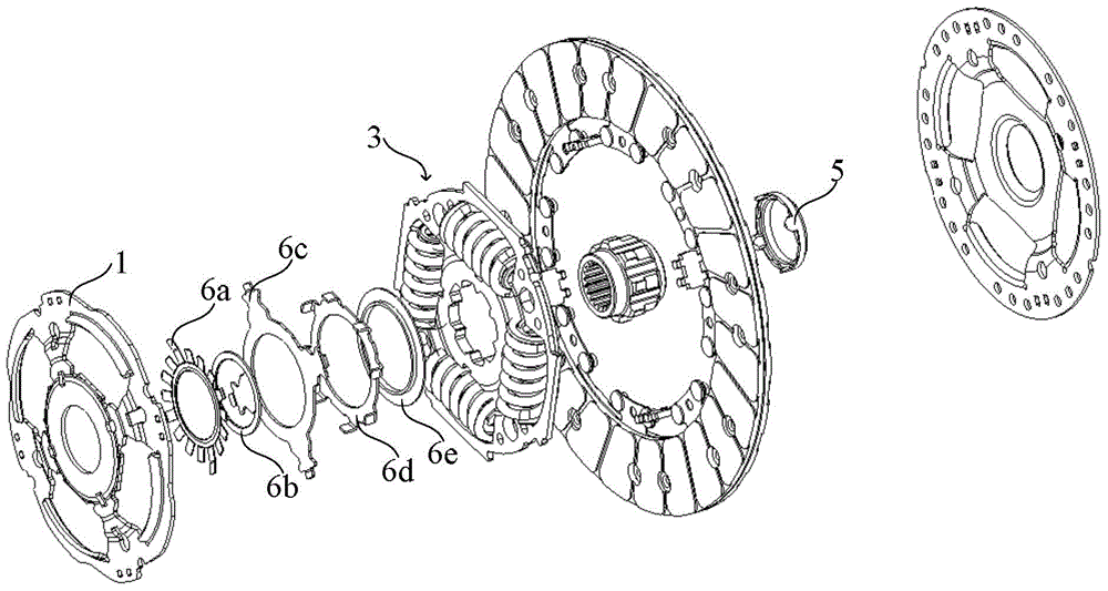
[0061] combine Image 6 As shown, the damping plate 41 has: t...


PUM


Abstract

The invention discloses a damping fin applied to a clutch driven disc, the clutch driven disc and a clutch. The clutch driven disc comprises a shock absorbing disc; a driven disc body fixedly connected with the shock absorbing disc in a torsion resisting manner; a driven disc hub rotationally positioned between the shock absorbing disc and the driven disc body and having a disc hub core; two damping fins positioned between the shock absorbing disc and the driven disc hub, extruded with each other and covering the disc hub core, wherein one of the damping discs is fixedly connected with the shock absorbing disc in a torsion resisting manner, the other one of the damping discs is fixedly connected with the driven disc hub in a torsion resisting manner, and the damping fins are annular, and have two opposite annular surfaces; and at least one projection part capable of generating elastic deformation on the surface, wherein the projection part has a slope extending from the top to the bottom in the peripheral direction. The clutch driven disc can solve the problems of complex structure, high cost and large rotating inertia in traditional clutch driven discs.

Description

technical field [0001] The invention relates to the technical field of clutches, in particular to a damping plate applied to a clutch driven plate, a clutch driven plate including the damping plate, and a clutch including the clutch driven plate. Background technique [0002] combine figure 1 with figure 2 As shown, the existing first clutch disc (clutch disc) includes: a damping disc 1; a driven disc body 2 fixedly connected to the damping disc 1 torsionally; The driven disc hub 3 between the driven disc body 2, the driven disc hub 3 includes a hub core 3a, and a flange 3b sleeved on the disc hub core 3a; The friction damping assembly in between, the friction damping assembly includes in sequence along the direction from the damping disc 1 to the driven disc hub 3: a diaphragm spring 4a, a support washer 4b and a damping plate 4c that are pressed against each other; The damping plate 5 between the body 2 and the driven hub 3 . [0003] The working principle of the clut...

Claims


Application Information

Patent Timeline
IPC IPC(8): F16D13/58F16D13/64
CPCF16D13/64F16D2300/22F16F15/1292
Inventor 陆周红
Owner SCHAEFFLER TECH AG & CO KG
Why Eureka
Try Eureka