Shell of differential speed variator for automobile
A technology for transmissions and vehicles, which is applied to transmission boxes, transmission parts, components with teeth, etc., can solve the problem that the reinforcing ribs cannot meet the strength requirements, and achieve the effects of saving materials, enhancing strength, and reducing costs.
- Summary
- Abstract
- Description
- Claims
- Application Information
AI Technical Summary
Problems solved by technology
Method used
Image

Examples
Embodiment Construction
[0010] Below by embodiment and in conjunction with accompanying drawing, the present invention will be further described:
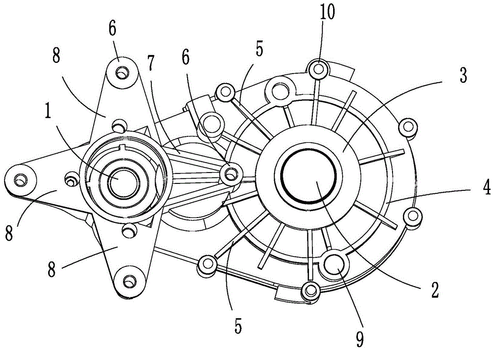
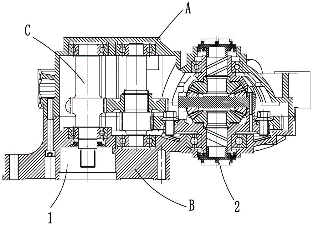
[0011] Such as figure 1 The vehicle differential transmission casing shown is mainly composed of a case cover and a case body, the two parts are fastened together and locked by six bolt and nut assemblies 10 . The case cover is provided with a power input hole 1 for installing a power input shaft, and a power output hole 2 for installing a power output shaft. Both the cover and the box body are aluminum castings, which are light in weight.
[0012] With the power output hole 2 as the center, an annular boss 3 and an annular rib 4 are arranged. The annular boss 3 surrounds the outer periphery of the power output hole 2 . With the power output hole 2 as the center of the circle, there are also strip ribs 5 distributed in a divergent shape. The inner end of each strip rib 5 is connected to the annular boss 3, and the outer end of some strip ribs 5 extends...
PUM
 Abstract
Description
Claims
Application Information
PatSnap Eureka turns technology decisions into work you can execute. Powered by our Innovation Knowledge Graph, it runs expert workflows across engineering, life sciences, materials and intellectual property. Get your review-ready output in minutes.


