
Camera flashlight assembly

A flashlight and component technology, applied in the field of lighting, can solve the problems of low screen resolution, narrow visual range, no display screen, etc., and achieve the effect of clearly displaying captured images, improving camera effects, and increasing screen size

Inactive Publication Date: 2015-07-22
SHENZHEN OCEANS KING LIGHTING ENG CO LTD +1
View PDF4 Cites 3 Cited by
  • Summary
  • Abstract
  • Description
  • Claims
  • Application Information

AI Technical Summary

Problems solved by technology

[0002] Existing flashlights with camera functions have the following two forms: the first type only adds a camera to the front light source attachment of the flashlight without a display screen
The second is to add a small display screen to the front part of the hand-held part of the flashlight body on the basis of the first flashlight. Because of the reason for the hand-holding, the hand-held part cannot be made too large, and the resolution of the screen is low. The viewing range is narrow, and it is difficult to see the captured image clearly during actual shooting
In actual application, some pipelines, narrow spaces, etc. need to be inspected by cameras, because the operator’s head cannot follow the camera flashlight into the narrow space, the above-mentioned camera flashlight cannot meet the requirements, and the operator does not know that he is taking pictures in actual use. Whether it can be clearly and effectively filmed, and the operation is inconvenient

Method used


Image

  • Camera flashlight assembly
  • Camera flashlight assembly
  • Camera flashlight assembly

Examples


Embodiment Construction

[0020] The following will clearly and completely describe the technical solutions in the embodiments of the present invention with reference to the accompanying drawings in the embodiments of the present invention. Obviously, the described embodiments are only some, not all, embodiments of the present invention. Based on the embodiments of the present invention, all other embodiments obtained by persons of ordinary skill in the art without creative efforts fall within the protection scope of the present invention.

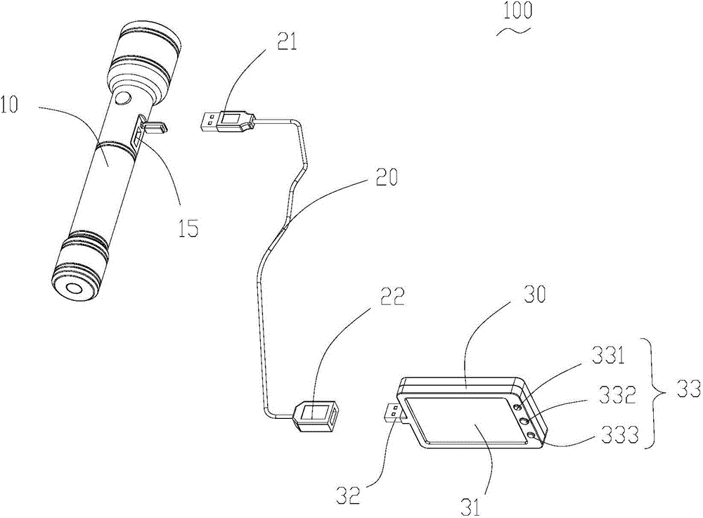
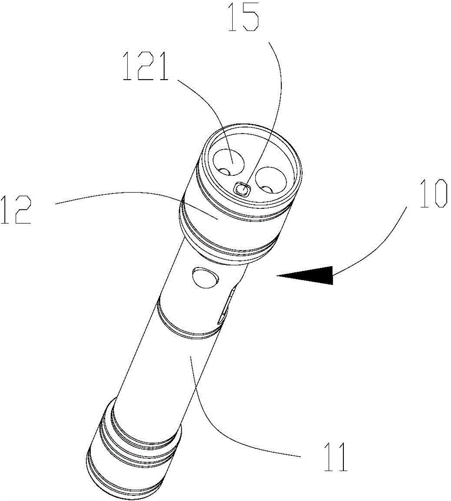
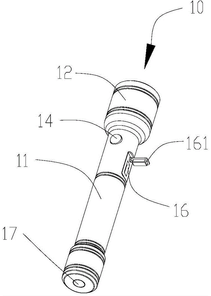
[0021] see figure 1 and figure 2 , the embodiment of the present invention provides a camera flashlight assembly 100 , which includes a flashlight 10 , a data cable 20 and a portable display 30 . The lamp head of the flashlight 10 is provided with a camera 15 and an interface 16 . The data cable 20 is plugged into the socket 16 and the portable display 30 so as to transmit the image irradiated by the camera 15 to the display 30 for display, which is convenient f...


PUM


Abstract

The invention provides a camera flashlight assembly. The camera flashlight assembly comprises a flashlight with a camera, a data line and a displayer. The displayer is provided with a plug, and is electrically connected with the data line or the flashlight through the plug so as to display an image shot by the camera.

Description

technical field [0001] The invention relates to a lighting field, in particular to a camera flashlight assembly. Background technique [0002] Existing flashlights with camera functions have the following two forms: the first type only adds a camera at the light source annex at the front end of the flashlight without a display screen. The second is to add a small display screen to the front part of the hand-held part of the flashlight body on the basis of the first flashlight. Because of the reason for the hand-holding, the hand-held part cannot be made too large, and the resolution of the screen is low. The viewing range is narrow, and it is difficult to see the captured image clearly during actual shooting. In actual application, some pipelines, narrow spaces, etc. need to be inspected by cameras, because the operator’s head cannot follow the camera flashlight into the narrow space, the above-mentioned camera flashlight cannot meet the requirements, and the operator does ...

Claims


Application Information

Patent Timeline
Patent Type & Authority Applications(China)
IPC IPC(8): F21L4/00F21V23/06F21V33/00H04N5/225F21Y101/02F21Y115/10
Inventor 周明杰姜涛
Owner SHENZHEN OCEANS KING LIGHTING ENG CO LTD
Learn More