Photosensitive plane target

A photosensitive surface and photosensitive technology, applied in the field of photosensitive surface target

Inactive Publication Date: 2015-07-22
张雅声
View PDF8 Cites 15 Cited by
  • Summary
  • Abstract
  • Description
  • Claims
  • Application Information

AI Technical Summary

Problems solved by technology

But like the prior art 3, the technical solution of the laser device does not involve the improvement and design of the facing target

Method used


Image

  • Photosensitive plane target
  • Photosensitive plane target

Examples


Embodiment Construction

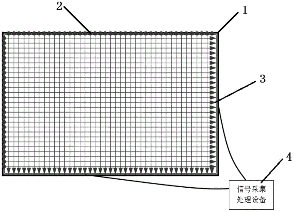
[0030] Such as figure 1 As shown, a photosensitive surface target described in this embodiment includes an outer frame 1, a laser emitting and receiving array, and a signal acquisition and processing device 4, wherein the laser emitting and receiving arrays are at least two groups, and two groups of lasers The emitting and receiving arrays are arranged crosswise on the outer frame, and the laser receiving end 3 of each group of the laser emitting and receiving arrays is connected to the signal acquisition and processing device 4 .

[0031] The laser emitting and receiving arrays are located on the same plane.

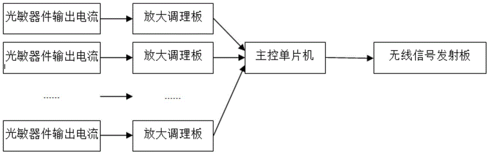
[0032] The laser receiving end 3 is a photosensitive element composed of several laser receiving elements arranged side by side. Each laser receiving element can generate a photosensitive signal with a high level output after receiving laser beam irradiation, and output Low level, the output signal of each laser receiving element is sent to the signal acquisition and p...


PUM


Abstract

The invention discloses a photosensitive plane target which comprises an outer frame, at least two laser transmitting and receiving arrays and signal acquiring and processing equipment. The laser transmitting and receiving arrays are arranged on the outer frame in a crossed manner, and a laser receiving end of each laser transmitting and receiving array is connected with the signal acquiring and processing equipment. The laser transmitting and receiving arrays are positioned on the same plane. The laser receiving ends are photosensitive elements, a plurality of laser receiving elements are arranged side by side to form each photosensitive element, each laser receiving element can generate photosensitive signals and output high level after laser beams irradiate on the laser receiving element, and can output low level when laser beams do not irradiate on the laser receiving element, and output signals of each laser receiving element are transmitted into the signal acquiring and processing equipment. The photosensitive plane target has the advantage that target hitting positions, the flight speeds and the flight direction of flying objects can be detected by the simple structural frame in high-speed collision tests.

Description

technical field [0001] The invention relates to a photosensitive surface target, which is used for measuring and analyzing flying objects during a high-speed collision test and belongs to the field of collision test equipment. Background technique [0002] There are not many systems for measuring and analyzing crash tests in the prior art, such as: [0003] Existing technology 1: The patent application number is 201410441054.1 and the published invention application titled "A New Type of Rolling Stone Impact Collision Test System" itself uses a loading frame, a loading motor, a screw lift, a load cell, and a spring loading sleeve. , guide sleeve, spring guide rod, spring, specimen loading head, specimen fixture, cylinder, specimen collision plate, bracket, high-speed camera and other equipment, the data acquisition mainly depends on the high-speed camera to collect images, and because the speed of the rolling stone itself is not High, so according to the inventor's inferenc...

Claims


Application Information

Patent Timeline
Patent Type & Authority Applications(China)
IPC IPC(8): G01B11/00G01P3/68G01P13/02
Inventor 张雅声李智杨露王磊张占月李怡勇魏巍宋旭民
Owner 张雅声
Why Eureka
Try Eureka